Basic Electronics And Microcontrollers: Difference between revisions
Dave Young (talk | contribs) |
|||
| (8 intermediate revisions by 2 users not shown) | |||
| Line 18: | Line 18: | ||
=== The 'Elements' of Electricity === | === The 'Elements' of Electricity === | ||
Below are the three fundamental (and important) concepts used when dealing with electricity in a scientific manner. There will be some formulas and such involved, but i'll try to keep it simple, and explain everything in plain english. But still it is important to become familiar with the 'math' involved. | |||
==== Electric Charge ==== | ==== Electric Charge ==== | ||
The electric charge is simply the amount of electrons involved. Since electrons are very very very tiny, and each one carries a very very very small amount of electric charge, it is impractical to measure charge by simply counting electrons. Sometime ago, [[wikipedia:Charles-Augustin_de_Coulomb|Charles-Augustin de Coulomb]] came up with the idea of defining amounts of charge as multiples (or fractions) of a really huge number of electrons. | |||
==== Electric Current ==== | |||
==== Electric Potential ==== | ==== Electric Potential ==== | ||
==== Electric Power vs. Energy ==== | |||
==== Electric Power vs. | |||
* Watts | * Watts | ||
* Joules vs. eV | * Joules vs. eV | ||
| Line 106: | Line 110: | ||
== Basic Electronic Components == | == Basic Electronic Components == | ||
An electronic circuit is nothing more, nothing less, than a collection of electronic ''components'' and the ''connections'' between them.<br/> | |||
Nowadays, electronic components exist in thousands of different types, flavours, shapes and sizes. This can be overwhelming and bewildering. However, it is nice to know that the vast majority of these (including [[#Discrete Components vs. Integrated Circuits|Integrated Circuits]], ar simply variations or combinations of a small set of basic components. These basic components are like the letters of the electronics alphabet. Everything else is built-up from them. | |||
Here is a PDF describing the basic components: | |||
[[Media:02-Electronic_Components.pdf]] | [[Media:02-Electronic_Components.pdf]] | ||
And here is a hierarchical list describing many, many varieties of the basic components: | |||
[[Basic_Electronics_And_Microcontrollers/Component_Hierarchy|Component Hierarchy]] | [[Basic_Electronics_And_Microcontrollers/Component_Hierarchy|Component Hierarchy]] | ||
=== Series and Parallel Circuits === | |||
=== Discrete Components vs. Integrated Circuits === | === Discrete Components vs. Integrated Circuits === | ||
| Line 116: | Line 129: | ||
=== Datasheets === | === Datasheets === | ||
= Designing Circuits & Circuit-Boards = | |||
Some notes & Hints on designing circuits & boards using Electronic CAD software like<br> | |||
[http://www.cadsoft.de/ Eagle] or<br> | |||
[http://kicad.sourceforge.net/wiki/index.php/Main_Page KiCad] | |||
= Microcontrollers = | = Microcontrollers = | ||
A [[wikipedia:Microcontroller|microcontroller]] | A [[wikipedia:Microcontroller|microcontroller]] | ||
=== Datasheets === | |||
* [http://www.atmel.com/dyn/resources/prod_documents/doc8271.pdf ATmega328 Datasheet] | |||
== Footnotes == | == Footnotes == | ||
<references/> | <references/> | ||
Latest revision as of 15:24, 22 November 2011
During the first Trimester (october - december 2010) I will be teaching a course in Basic Electronics and the use & programming of Microcontrollers. The theory-lessons will take place on wednesday afternoons, and additionally there will be some Electronics Hacking Days (see the Calendar)
Basic Electronics
In order to hack existing circuits, or to design and build your own, some understanding of the fundamental principles of electronics and circuit-design are required.
Although the trial-and-error approach (i.e. Circuit-Bending) can be fun and rewarding, it can also be frustrating (connecting the wrong points together will usually destroy a circuit), and dangerous (never touch a circuit that may have voltages higher than ±25V going on!).[1]
Even after successfully 'bending' a circuit you wil not have learned how the circuit works, really, or why it behaves differently if you connect this point to that point ant touch it there. "It just does".
So, let me explain a bit about electronic circuits. It will be useful knowledge, I think.
What is Electricity?
The word 'Electronic' actually means "having to do, or working with electrons". In that same context, 'Electricity' is "the behaviour of electrons". This is the case for devices like an Electron microscope or a Photo multiplicator tube that are designed to detect the arrival of a single electron, but aslo for phenomena like lightning where uncountable bazillions of electrons are exchanged, in a flash, between charged thunderclouds or, most spectacularly, between the clouds and the Earth.
Electricity is a form of energy, and as such comes in two distinct states; Potential energy, i.e. electric potential, a.k.a. voltage (electrons wanting to move) and kinetic energy, i.e. electric current (electrons moving). Potential energy will get converted into kinetic energy whenever possible. In other words; if an electric current can flow, it will. In this conversion, some or all of the energy becomes available to do 'work'. An electric current has the power to do something. Converting kinetic energy back into potential energy is also possible, but then this requires 'effort' (the opposite of 'work', in this context). In order to (re-)charge a source of potential energy, power is required.
The 'Elements' of Electricity
Below are the three fundamental (and important) concepts used when dealing with electricity in a scientific manner. There will be some formulas and such involved, but i'll try to keep it simple, and explain everything in plain english. But still it is important to become familiar with the 'math' involved.
Electric Charge
The electric charge is simply the amount of electrons involved. Since electrons are very very very tiny, and each one carries a very very very small amount of electric charge, it is impractical to measure charge by simply counting electrons. Sometime ago, Charles-Augustin de Coulomb came up with the idea of defining amounts of charge as multiples (or fractions) of a really huge number of electrons.
Electric Current
Electric Potential
Electric Power vs. Energy
- Watts
- Joules vs. eV
The Laws of Electricity
Ohm's Law
The process of the conversion from potential to kinetic energy, the relationship between voltage, current and resistance (i.e. the difficulty of the conversion) is given by Ohm's Law:
<math>V = I \cdot R</math> or <math>I = \frac{V}{R}</math> or <math>R = \frac{V}{I}</math> where V, the potential, or voltage, is expressed in Volt (V), the current I in Ampère (A), and the resistance R in Ohm (Ω)
Basically, this states that the potential converted (the voltage 'lost') in a given resistance is equal to the current times the resistance,
the current flowing through a given resistance is equal to the potential-difference across the resistance (the voltage 'lost' in the resistance) divided by the resistance, or
the resistance is equal to the voltage-difference across that resistance divided by the current.
All three versions are different perspectives on the same situation, and are equivalent.
In practical terms, say that the resistance is infinite. Then <math>I = \frac{V}{R}</math> states that the current will be zero, irrespective of the voltage. This is an 'open circuit'; no current can flow, because the resistance to current is infinite. All the potential energy is contained, and no kinetic energy exists. Inversely, if the resistance is 0Ω, <math>I = \frac{V}{R}</math> dictates that the current should be infinitely high. This is a 'short circuit', a situation best avoided, because all the potential energy is converted into kinetic energy, instantly, and this is usually not a good idea.
For any resistance-value in between these two extremes, some potential energy is converted into kinetic energy. Exactly how much energy is converted can be calculated if any two values of V, R and I are known.
Joule's Law
The amount of power that is involved in these electric currents is given by Joule's Law:
<math>P = V \cdot I</math> where P, the power, is expressed in Watt (W)
Substituting Ohm's equation in Joule's equation lets us calculate the power when the resistance and either I or V are given:
<math>P = I^2 \cdot R</math> or <math>P = \frac{V^2}{R}</math>
Water-equivalent Circuits
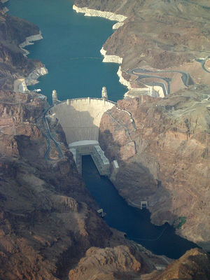
This is all rather abstract, so let me introduce a favourite analogy that I will use throughout this course: Think of water-systems instead of electric systems.
To most people, electricity & electrons are very abstract concepts. Hard to visualise and grasp. But everybody will be immediately familiar with water and how it behaves, from lifelong personal experience. In these water-systems that I will be introducing throughout the course, potential energy, voltage, is analogous to the pressure of the water and kinetic energy, current, is analogous to the flow of water.
Imagine an artificial lake, high up in a remote mountain gorge somewhere, with a dam straddling the gorge. The water in the lake wants to flow downhill, because of gravity, but it can't, because of the dam. If the dam were a solid wall of concrete, all of the water in the lake would be contained. More specifically, all of the potential energy of the water would be contained. The water can't flow anywhere. This is the 'open circuit' equivalent.
But this would be pointless. That is not why the dam is there. In fact, the dam has a hole at the bottom, with a pipeline leading all the way down to the mouth of the valley, where there is a building containing turbines & generators & such. Some water can escape from the lake, through the hole in the dam, and flow into the pipe. On the way down, this water's potential energy is traded for kinetic energy, and by the time it arrives in the generator-building, the water is moving fast and with considerable momentum. The 'work' that this water may do is traded for the 'effort' needed to push the turbine-blades and turn the generator. The generator converts this kinetic (rotational) energy back into potential (electric) energy, and there will be a voltage available at the terminals of the generator. The flow of the water is resisted when it meets the blades of the turbine. In fact, the amount of resistance of the turbine is directly related to the amount of 'effort' required to turn the generator, which in turn is dependent on the amount of electric power the generator has to deliver.[2]
The water, having spent most of its kinetic energy, will gently flow out of the generator-building, into streams & rivers and eventually into the sea. For the water, the sea is the point of lowest potential energy from where it cannot flow further down. The 'zero potential' level.
Imagine that it doesn't rain for quite a while. Eventually the lake will run dry. All of the potential energy in the lake will have been converted into kinetic energy, and the source of potential energy will have been depleted. Like an empty battery.
But of course in reality it does rain, and any rain or snow that falls in the surrounding mountains above the level of the lake must have an even higher potential energy than the water in the lake. This energy actually comes from the sun, evaporating water from the land & sea, which forms clouds high up in the air. The wind (also a result of the energy from the sun) will drive these clouds against our mountain-range, where the clouds are pushed upward into colder strata of the atmosphere. The clouds will condensate into water-droplets or snowflakes falling on the mountains and thus re-filling the lake.
Now imagine a catastrophic collapse of the dam. The dam breaks and no longer offers any resistance to the potential energy of the water in the lake. All of the water will suddenly come crashing down the mountain, with all of its potential energy converted into kinetic energy, wiping out any obstacles it finds in its path, and doing massive damage until it eventually raches the sea. This would be a 'short circuit' situation. Not a good thing to have happen, then.
This is an example of a 'water circuit', since you can visualise it always being the same water getting evaporated from its level of lowest potential into clouds (the level of highest potential in this circuit), then raining down into the lake, flowing down the pipeline to drive the generators, and flowing back to its level of lowest potential. Over & over again.
As a thought-experiment, this mountain lake example demonstrates the conversion of potential into kinetic energy (and back), the concept of resistance to flow (or current), the ideas of 'work' vs.' effort' and power. It describes the 'open circuit' and 'short circuit' equivalents, and the fundamental concept of a circuit, so called because the 'agents' involved (ie. water or electrons) travel round and round in a loop, over & over again, until the ultimate source of potential energy (in this case the sun), is depleted.
Electronic Circuits
An electronic circuit is basically a loop, or a set of interconnected loops, where electric currents flow from points of higher potential, through the components of the circuit, to points of lower potential. The potential differences in a circuit are the driving force behind the electric currents. The points of highest & lowest potential in a circuit are provided by a power-source, a battery or a power supply.[3] Electric current will flow from the plus (+) side of the power-source through the circuit and eventually back to the minus (-) side of the power-source.
Inside the power-source, however, an electric current is forced from the minus to the plus. This process, the re-charging of the electrons' potential energy, requires 'effort', and the 'work' is usually done by chemical reactions (in batteries), conversion of other sources of kinetic energy (in generators), the photovoltaic effect (in solar cells), or the conversion of electric current provided by another source of electric potential (like the 230V AC from a wall-socket).
Note that the flow of electricity is defined as flowing from points of higher potential (more +) to points of lower potential (more -). However, the 'agents' involved, the electrons, are themselves negatively charged particles, and their direction of flow is in the opposite direction (from - to +).
This is highly confusing, and I sincerely apologise on behalf of Allesandro Volta et al., who discovered the battery without being aware of the existence of electrons, and thus had a 50% chance of guessing the direction of flow correctly.[4]
Circuit Diagrams
A circuit diagram is a graphical, symbolic representation of a circuit, on paper or on a computer-screen. Such a digram is an accurate description of the circuit, in a highly formalized symbolic language. The advantage of a circuit diagram is that the workings of the circuit can be understood, and the voltages and currents in the circuit, as well as other properties of the circuit, can be calculated and figured out without having to build the circuit. In fact, designing a circuit of any complexity without first making a diagram of the circuit would be an undertaking doomed to failure.
The disadvantage of circuit diagrams is the formalized symbolic language. the symbols used to denote the components of a circuit do not look anything at all like the components' physical appearance in the real world. A further complication is that (at least) two official sets of symbols are in common use today: the 'old' NEMA/IEEE/ANSI symbols, still in common use in the US & Japan, and the 'new' IEC/DIN/ISO symbols used in Europe.
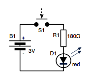
A simple diagram, of a battery-powered LED light for example, is easy to understand.
But a diagram of a complex circuit, like a late 80's television for example, with hundreds of components, can quickly become overwhelming and bewildering. That is why such diagrams are usually hierarchical. The circuit is broken down into functional blocks, each of which has its own diagram, and then there is a 'block diagram' showing how these blocks are interconnected.
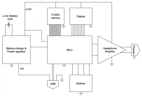
Here is a block-diagram:
Can you guess what this circuit does?
One thing to note here is the multiple appearance of this symbol: ![]() This denotes the 'Ground' connection, the point of zero potential in the circuit.[5] All of the ground points are connected together. The use of the Ground symbol makes it easier to draw diagrams, because without it, there would have to be regular lines connecting all the ground points in the circuit together, and usually there are lots of those. It is also common practice to use a symbol instead of the power-source lines, usually an arrow <math>\uparrow</math> with some text denoting which power-supply line that point in the circuit is connected to.
This denotes the 'Ground' connection, the point of zero potential in the circuit.[5] All of the ground points are connected together. The use of the Ground symbol makes it easier to draw diagrams, because without it, there would have to be regular lines connecting all the ground points in the circuit together, and usually there are lots of those. It is also common practice to use a symbol instead of the power-source lines, usually an arrow <math>\uparrow</math> with some text denoting which power-supply line that point in the circuit is connected to.
Soldering Circuits
Nowadays electronic circuits are made by soldering the components that make up the circuit onto a circuit board that usually has pre-printed copper traces that form the connections between the components. But it wasn't always that simple. In the early days of electronics (the 30's & 40's), components were big and bulky, mostly relays[6], transformers, huge capacitors, resistors the size of small sausages or pickles, and of course vacuum tubes. The components were bolted onto rails or racks, or, in the case of components that could wear out and might need to be replaced, placed in sockets, where the sockets were bolted onto rails or racks. The components were then connected together in a point-to-point fashion by bundles of wires, and the ensuing spaghetti-like cluster of wires was called a wiring-harness.
A little later, in the 50's and early 60's, components became smaller, and it became feasible to use strips or discs of non-conductive material with parallel rows of solder-terminals and solder the components between opposing pairs of terminals. Strips of these type were called Turret boards. They still had to be interconnected with wires, using the old wiring-harness method.
But then pre-printed circuit-boards gradually took over, since it became clear that the extra time and effort involved in first designing and producing the boards quickly payed off in terms of time saved in assembling the circuits and saving on vast quantities of wire. In the late 70's, machines were designed for automating the process of sticking the components on the boards (a process called 'populating' the board) and soldering a whole board in one go by simply setting it afloat in a vat of molten solder for a few seconds.
Up to this point, all the electronic components had legs or leads that were supposed to be inserted into holes in the circuit board. The components are placed on the topside of the board, with the leads going through the holes, and then soldered to little copper islands (a.k.a. pads) on the underside of the board. But it soon became apparent, as components kept getting smaller and smaller, that quite a bit of board-space (and manufacturing time) was wasted on all the legs and the holes, and someone came up with the idea of soldering the components to the surface of the board. No more need to drill holes, and the legs of te components could be much smaller, shorter and closer together.
Of course, some holes were still needed in multi-layered boards, where the copper traces are not only placed on one side of the board, but on both sides, or even in intermediate layers inside the board. Whenever a copper trace on one layer needs to be connected to a trace on another layer, a hole is drilled. Then, using an electrochemical process, a layer of copper is deposited on the inner surface of the hole, connecting together all coper traces that meet at the hole. Such a hole is called a 'via'
For the circuits we will be building during this course, we will be sticking to the good old through-hole technology as much as possible. Surface-mount components are very, very tiny, with their legs very close together, and they are quite difficult to solder by hand. However, this may be tricky, because some modern components are only available in SMD packages nowadays. There is a workaround for this problem though; SMD-adapters. These are little circuit boards where you can solder an SMD-component on top, and then have pins or wires coming off the edges of the board that would fit in a standard 0.1-inch through-hole grid. It still requires soldering of the SMD-component in question, though.
Also, with through-hole components we can use a breadboard, perfboard or stripboard, so we won't have to pre-fabricate circuit-boards. Although sometimes it is better to make a circuit-board for your circuit, especially if you need more than one instance of the same circuit, and I will show you how circuit-boards are designed and made.
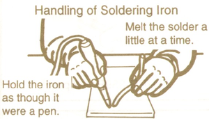
Here's a PDF I wrote on how to solder (through-hole) components onto a circuit-board:
Media:01-Soldering.pdf
Of course, you are welcome to try different techniques, if you like. For small, simple circuits, the ancient point-to-point technique can be esthetically pleasing, although the result will probably be very fragile.
Basic Electronic Components
An electronic circuit is nothing more, nothing less, than a collection of electronic components and the connections between them.
Nowadays, electronic components exist in thousands of different types, flavours, shapes and sizes. This can be overwhelming and bewildering. However, it is nice to know that the vast majority of these (including Integrated Circuits, ar simply variations or combinations of a small set of basic components. These basic components are like the letters of the electronics alphabet. Everything else is built-up from them.
Here is a PDF describing the basic components: Media:02-Electronic_Components.pdf
And here is a hierarchical list describing many, many varieties of the basic components: Component Hierarchy
Series and Parallel Circuits
Discrete Components vs. Integrated Circuits
Analog IC's
Digital IC's
Mixed-signal IC's
Datasheets
Designing Circuits & Circuit-Boards
Some notes & Hints on designing circuits & boards using Electronic CAD software like
Eagle or
KiCad
Microcontrollers
Datasheets
Footnotes
- ↑ A Photo-flash is a prime example. They usually work on 2 AAA-size batteries, so you'd think they are harmless when touched, right? Wrong! the circuit inside contains a converter wich makes a very high voltage, usually somewhere around 400V! And worse, it has a capacitor that stores a considerable charge at that high voltage. Very nasty & painful when touched. Use extreme caution!
- ↑ The pipeline from the dam to the generator-building offers some resistance to the water as well, because of friction with the inner wall of the pipe. But if the pipe's diameter is big enough, this resistance is negligible compared to the resistance of the turbine.
- ↑ Exceptions to this rule are the circuits inside power-supplies. These generally convert electric energy from another source (on the 'primary' side of the power-supply) to a power-source suited for the circuit being powered (from the 'secondary' side of the power-supply). It is not always the case that the primary has a higher potential than the secondary, though.
- ↑ I suspect that he chose to call the copper plate of his battery the plus, and the zinc plate the minus, simply because copper looks prettier than zinc. He was Italian, after all.
- ↑ The 'ground' is not necessarily the point of lowest potential in a circuit. Negative potentials may exist also. The ground is simply, by agreement, the point of zero potential. All potentials in a circuit are calculated or measured with respect to ground.
- ↑ The old electromechanical relays are becoming extinct, but some great fun can be had with them. Especially if you have lots of them

