Category:LFP: Difference between revisions
Andre Castro (talk | contribs) |
(→Pages) |
||
| Line 16: | Line 16: | ||
** [[LFP_Max]] | ** [[LFP_Max]] | ||
** [[LFP_Anna]] | ** [[LFP_Anna]] | ||
** [[LFP_Tisa]] | |||
= Low Frequency Publication = | = Low Frequency Publication = | ||
Revision as of 17:29, 28 November 2019
Publication Table of Contents
script
Git repo of Script: https://git.xpub.nl/XPUB/special-issue-x-pubscript
- clone:
git clone ssh://git@git.xpub.nl:2501/XPUB/special-issue-x-pubscript.git
- install dependencies
- run
Pages
Pages must include [[Category:LFP_Publication]]
Low Frequency Publication
Materialising the Blackbox
Introduction
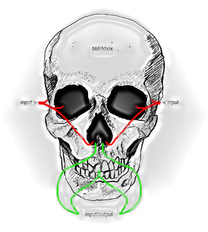
In this special issue we will explore the physicality behind slick black boxes as for example found in everyone's pockets today. Be it hardware or software. The goal is to make the interactions, interfaces and connections explicit through hands-on research and play. Informed by the fact all modern day electronics still adhere to the paradigm of modularity, like the earliest computer designs we will collaboratively build one or more devices that explore notions of modularity, complexity/simplicity, interfaces, darkpatterns, input/output while explicitly giving insight into the black box, but this time including a manual.
To encourage affection with the materiality of the blackbox we will create our own. Starting of by constructing the building blocks of a synthesizer, allowing the creation of complex outputs by interfacing/combining relatively simple operations. As a clear framework we will start off by working with sound, your fastest sensor. Compatible with the possibly familiar 'Eurorack' format (as developed by Doepfer) we will be constructing several electronic modules that allow the output of one module to be the input for the next. Expanding upon the original discrete, or analog approach, each of our modules offer a programmable interface, eventually allowing for interfacing beyond the blackbox.
As single modules perform one job and one job well, you will have to anticipate and even require the output of someone elses module in order for yours to work. Coinciding with your research we will create one or several 'outputs' consisting of an interface, electronics and a manual.
Guests
Dennis de Bel Dennis de Bel (1984, NL) is an applied artistic researcher, educator, radio amateur (call sign PD0WNED). In his practice he positions himself as producer, consumer, observer and distributor of critical knowledge focussed on technology. His work has been exhibited at Siggraph Los Angeles, Transmediale Berlin and hosted workshops in various collaborations at, for example, ISEA Hong Kong, Radical Networks New York. He participated in the Relearn summer schools and Libre Graphics Meetings besides being a guest tutor at the Design Academy Eindhoven and the Willem de Kooning Academy Rotterdam University of Applied Science. In 2017 he co-founded Varia, a Rotterdam based space for developing collective approaches towards everyday technology. De Bel holds a MA from the Piet Zwart Institute (NL) and most recently (Jul-Dec 2018) participated in the artist in residency program of the Institute for Provocation in Beijing.
Olli Aarni
Olli Aarni (Oulu, Finland) makes experimental electronic music with vivid timbres and textures, static and slippery harmonies. He has released more than 20 records on four continents with labels like Aguirre, Flau and Lal Lal Lal. He has played in various European countries and Japan at events such as Flow Festival (Helsinki, Finland), Jauna Muzika (Vilnius, Lithuania) and The Gathering of Trans-Medial Publishers (Antwerpen, Belgium).
Aarni holds an MA in Finnish Language. Combining his passion for linguistics and music, he has created a sound poetry piece, consisting of the Finnish sound alphabet, and two sound poems created with this alphabet. He has created music with plants as part of the multimedia artist group Band of Weeds. Currently he is working on a site-specific music piece for electronic instruments and the Finnish traditional instrument kantele.
de Player Nor a white cube (read gallery) or black box (read: theater) but a 'grey dome' where production meets performance meets possibilities..and everything in between http://deplayer.nl
Martin Howse Not sure where to begin, techno-shaman would cut his practice short. Check his 'micro research' here: http://www.1010.co.uk/
Schedule
The program consists of three main sections, building, interfacing and coding and going public. Bring headphones to every class!
Building
Getting your hands dirty.
Week 1 - Sept 17
Today you will become modules of a modular synth! First we need to construct them though:
Construct: Meergranen (Optionally + LFO)
pad: https://pad.xpub.nl/p/lfp1 (Keep build notes, address points of improvements, happy accidents and tips)
git: https://git.xpub.nl/XPUB/special-issue-x
build manual: File:Manual-meergranen.pdf (20MB PDF)
BEFORE YOU POWER YOUR MODULE, LET ME TAKE A LOOK
arduino firmware: Arduino Firmware (ZIP file)
software: Arduino IDE + Driver
PLEASE BRING A MINI USB CABLE (with power + data lines) and Headphones (3.5mm jack)
homework:
-Play with the various Arduino Firmware (ZIP file) found in that zip file. Note some codes might need an external trigger (control voltage, 0-5v) in order to produce sound. Other codes might only produce triggers (no sound), used to sequence/trigger other modules. Make notes on the pad above what you find interesting, what functionality you would like to have, what sounds?
-Record your own sample, using the 'Memphis' example firmware and script below: http://pzwiki.wdka.nl/mediadesign/Category:Lfp#Adding_custom_audio_samples
Week 2 - Sept 23,24,25,28
Workshop with Olli Aarni
Notepad: https://pad.xpub.nl/p/olliworkshop
During the first part of the workshop the participants will learn about different interfaces of making sounds and music. We will explore such questions as: How do restrictions lead to creative solutions? How does technology affect the outcome of the creative process? How does the interface itself relate to its output?
We will listen to different sounds and develop our own concepts and categories for understanding, grouping and creating sounds. The process will combine language and sound in order to create a unique categorisation system, which will be used later as a basis for building a modular sound producing system.
Furthermore there will be a small introduction into modular synthesis and practical logic concerning your modules and demo of various in's and out's
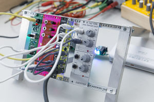
Demo setup
28th September Excursion to Dutch Modular Festival
Please add your name if you are attending:
Dennis de Bel
Mika Motskobili
Mark van den Heuvel
Ioana Tomici
Week 3 - 1 Oct
Morning (Individual)
Afternoon (in groups of two)
Assignment (in groups of two)
- Create a sample containing various sounds (within 3sec, 8000Hz) or use one that already has these characteristics, upload to one of your modules.
- On a second module, write a code that can sequence / play the different parts of this sample individually, using analogWrite. Hints 1, 2
- Upload to GIT (exercises/trigger/yourgroupname )
Extended
- Use built in potentiometers to control control voltage: https://git.xpub.nl/XPUB/special-issue-x/src/branch/master/basics/simple-pwm-led-audio/
Week 4 - 8 Oct
[pad] https://pad.xpub.nl/p/xpub1temp
[hardware] PSU building, scavenge for 'test' case
Interfacing
designing interfaces (frontpanels)
Laser cutter instructions (PDF)
Frontpanel source files (vector)
Week 5 - 15 Oct
Workshop with Olli Aarni (14, 15, 16)
[PAD last week] https://pad.xpub.nl/p/xpub1temp2
[PAD this week] https://pad.xpub.nl/p/olliworkshop2
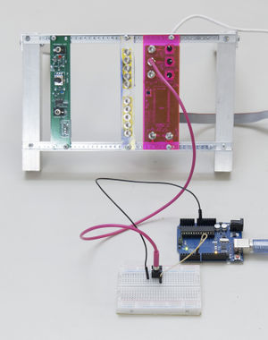 Meergranen is easily interfaced with another (kind of) Arduino....duh
- Recommended reading:
- John Cage: Silence https://monoskop.org/images/6/6b/Cage_John_Silence_Lectures_and_Writings_1973.pdf
- Pauline Oliveros: Deep Listening - A Composer's Sound Practice
- Mark Bain, Psychosonics and the Modulationof Public Space, On Subversive Sonic Techniques
Week 6 - 5 Nov
Recap+Check with DEPLAYER at Varia (gouwstraat 3)
[pad] https://pad.xpub.nl/p/xpub15112019
Week 7 - 12 Nov
Develop interactions
- DE PLAYER workshop Friday 15.11
- DE PLAYER workshop Thursday 28.11
Publishing
Going public, manual
Week 8 - 19 Nov
Week 9 - 26 Nov
Week 10 - 3 Dec
Presentation at de Player
Resources
Software
http://pzwiki.wdka.nl/mediadesign/Arduino101
Some theory behind PWM and max resolution/sample rate: http://www.openmusiclabs.com/learning/digital/pwm-dac/
More on timers: https://hackaday.io/project/11957-10-bit-component-less-volume-control-for-arduino
In-depth look into PWM and Timers on Arduino Nano https://makezine.com/projects/make-35/advanced-arduino-sound-synthesis/
Text to Speech on Arduino
The Talko/Talkie library has a limited vocabulary and uses a weird file format for the sound samples (vocabulary). The text to speech library below is an attempt to synthesize speech using predefined tones to construct words, offering virtually endless (English) vocabulary (Would be nice to create a different language....). There are some caveats: It works but requires a hardware modification (it doesnt work on pin11), in addition, the sound is VERY roboty, barely understandable. To test it out you don't have to modify the hardware, but you need to know what pins on the PCB you need to hook up to a speaker.
Install Library
- clone repo or download zip here > https://github.com/jscrane/TTS
- unzip, rename TTS-master to TTS and copy to ~/Documents>Arduino>Libraries>TTS
- restart arduino ide
- when restarted open File > Examples > TTS > TTStest
- change the PWM output pin from 3 to 10 (ez to find on the pcb, its under the normal output pin 11 ;)
so from:
 // Media pins
 #define PWM 3
to :
 // Media pins
 #define PWM 10
Upload!
Test it out the sound by clipping a wire to the outside of the output jack (ground) and to pin 10 (one underneath the normal output pin 11)! Be careful not to touch other pins/connections.
Hardware mod
To make it semi permanent, cut the trace from pin 11 with a sharp knife. Solder a wire from pin 10 to resistor R9. The resistor is a part of a low pass filter and possibly needs modification for this particular sound as well (there is a lot of high frequency noise in the signal). There is more info on the specifics here: https://github.com/jscrane/TTS
Hardware
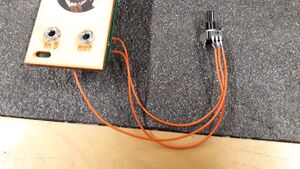
Modules - Mult
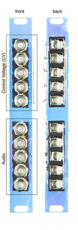
A simple module; just a front panel and jack sockets connected to each other (tip to tip (+), sleeve (gnd) to sleeve). Creating a passive (non-powered/buffered/unsafe) crude kind of mixer!
Notice the two sections of five jacks, distinguishing audio from CV. This is for safety, since our 'Meergranen' output (audio) is not protected from potential control voltages of -12v to 12v.
SO always try to mix audio with audio and CV with CV (if you have spare arduinos you can igonre this message, because modulating audio with CV can be interesting!).
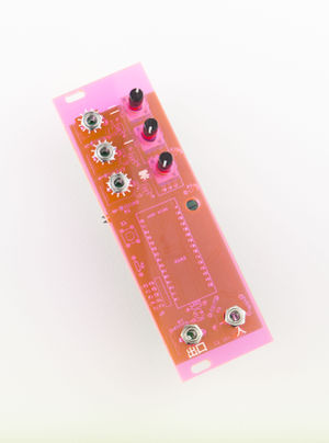
Modules - Arduino Tool 'Meergranen'
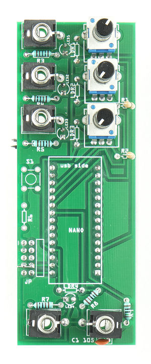
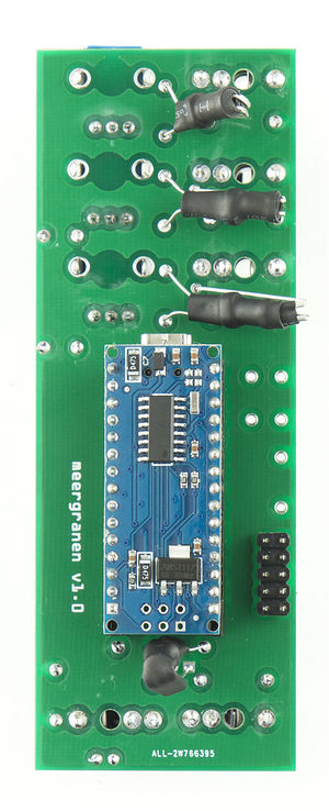
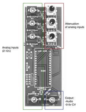
Meergranen, front+back, no frontpanel
NOTE: there is a bug in the IDC connection, pin 7 and 8 need to be bridged if you want to power the module through usb (for testing)
NOTE: the optional button is wired incorrectly and is not usable. It needs a jumper from 5v (arduino) pin and a jumper to any of the free digital pins see.
WARNING: the output port is UNPROTECTED agains overcurrent/voltage/reversepolarity. Use it as OUPUT and dont connect it to another output for example.
What can the jack inputs do?
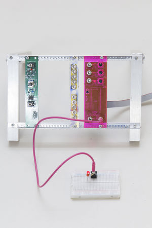
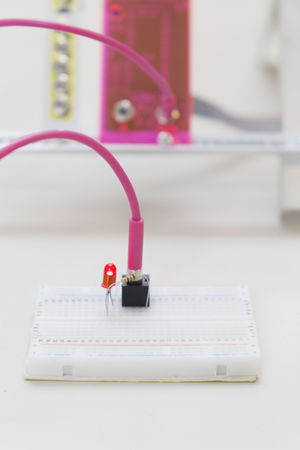
The output of Meergranen (audio or PWM) delivers about 5v. Enough to easily light a LED (or activate another Meergranen!)
Adding custom audio samples
Download Arduino firmware examples here: Arduino Firmware (ZIP file) In the zip file you will find grains-sounds-master.zip, unzip and flash one of the arduino sketches found in the 'patches' folder. Grains-sounds is a basic sample player that allows you to manipulate pitch, start and end of a sample (using the potentiometers or control voltage). To add your own samples, just replace the 'sample.h' file with one of your own. To prepare an audio sample for this firmware:
-install sox (and Audacity ) (mac: install homebrew and then install brew install sox)
-make 3 second (loop) of a sound in Audacity for example
-convert stereo sound to mono
-export as wav file (16bit)
-in Terminal, navigate yo your exported soundfile and convert it to 8bit, 8000hz: (alternatively use the script below to convert your 16bit wav file exported from Audacity directly to sample.h!)
 sox your_sound_file.wav -t u8 -c 1 -r 8000 output.wav
 xxd -i output.wav > sample.h
you end up with a hexadecimal encoded soundfile now in an array.
C code needs to know the length of the array before hand:
at the bottom of sample.h it says the length of the file,
for example 27278.
in sample.h search and replace the first line:
unsigned char out2_wav[] = {
with, note you have to change the sound_lenght into that of your sample:
 #define SAMPLE_RATE 8000
 const int sound_length=27278;
 const unsigned char sound_data[] PROGMEM= {
Script
You can use this bash script to automatize the creation of sample.h (instructions below):
#!/bin/sh
# Prepares a sample.h file
# sed not used, should just werk (TM) everywhere
# Usage: ./samplify.sh my_sample.wav
# Or you can install samplify.sh in your ~/bin and call it
# from anywhere you like

# Convert original soundfile and create sample.h
# A temp file is needed oftherwise xxd is unable to generate
# sample length information?
sox "${1}" -t u8 -c 1 -r 8000 /tmp/sample.wav
xxd -i /tmp/sample.wav > sample.h
rm /tmp/sample.wav

# Extract sample length
SAMPLE_LEN=$(tail -1 sample.h | cut -d ' ' -f 5 | tr -d ';')

# Inject SAMPLE_LEN in new file header
NEW_HEADER="#define SAMPLE_RATE 8000
const int sound_length=${SAMPLE_LEN};
const unsigned char sound_data[] PROGMEM= {"

# Remove first line of sample.h
echo "$(tail -n +2 sample.h)" > sample.h

# Prepend new header to sample.h
echo "$(echo "${NEW_HEADER}"; cat sample.h)" > sample.h
The latest version will be updated on the trimester's git repos! https://git.xpub.nl/XPUB/special-issue-x/src/branch/master/utils/samplify.sh
How to use the script: Copy paste the text above in a texteditor (raw text, not Textedit) and save as 'samplify.sh'. Open a terminal and make the file executable:
chmod +x samplify.sh
Put your wave file in the same directory as samplify.sh and in terminal run:
./samplify.sh yourfile.wav
This will generate the sample.h file needed for the sample player arduino firmware as in the 'memphis' example. Just replace the sample.h in that folder with your newly generated one. Flash the arduino with the memphis code again and it should now play our own custom sample!
Pro tip: 27278 bytes is about the maximum lenght of sample storage on arduino nano (+ the script that plays the sample). If sound sample is a bit too long/big you can simply speed it up in Audacity, the script allows for pitch bending, so you can make up for the increase in speed. Possiblt there is some head room in the sample rate (8000hz) in the above example. Reducing this will result in smaller file, but lower quality (resolution). Possibly the playback speed will increase as well (since the script anticipates the sample rate of 8000hz, ofcourse this is adjustable by yourself).
Bill of Materials
| Label | Part Type | Properties |
|---|---|---|
| for arduino | Male Headers | 1x16 |
| for arduino | Female Headers | 1x16 |
| C1 104 | Capacitor | 104, 100nF package cap-pth-small2; variant pth2 |
| J1 - A2 | 3.5mm Switch Jack | size 3.5mm; variant 1; part # PJ301M-12 |
| J2 - A1 | 3.5mm Switch Jack | size 3.5mm; variant 1; part # PJ301M-12 |
| J3TRIG - A3 | 3.5mm Switch Jack | size 3.5mm; variant 1; part # PJ301M-12 |
| J4 - A0 | 3.5mm Switch Jack | size 3.5mm; variant 1; part # PJ301M-12 |
| J4 OUT | 3.5mm Switch Jack | size 3.5mm; variant 1; part # PJ301M-12 |
| JP | Header 5x2 | package 2x5-ra; variant ra |
| LDR1 | Photocell (LDR) | resistance@ dark 300 kOhms@ 10 seconds; package THT; resistance@ luminance 16 kOhms@ 10 lux |
| LDR2 | Photocell (LDR) | resistance@ dark 300 kOhms@ 10 seconds; package THT; resistance@ luminance 16 kOhms@ 10 lux |
| LDR3 | Photocell (LDR) | resistance@ dark 300 kOhms@ 10 seconds; package THT; resistance@ luminance 16 kOhms@ 10 lux |
| LDR4 | Photocell (LDR) | resistance@ dark 300 kOhms@ 10 seconds; package THT; resistance@ luminance 16 kOhms@ 10 lux |
| LED1 | Red (633nm) LED | package 3 mm [THT]; color Red (633nm); leg yes |
| LED2 | Red (633nm) LED | package 3 mm [THT]; color Red (633nm); leg yes |
| LED3 | Red (633nm) LED | package 3 mm [THT]; color Red (633nm); leg yes |
| LED4 | Red (633nm) LED | package 3 mm [THT]; color Red (633nm); leg yes |
| NANO | Arduino Nano (Rev3.0) | type Arduino Nano (3.0) |
| P1 = A2 | Rotary Potentiometer (Small) | package THT; size Rotary - 9mm; track Linear; maximum resistance 10kΩ; type Rotary Shaft Potentiometer |
| P2 = A1 | Rotary Potentiometer (Small) | package THT; size Rotary - 9mm; track Linear; maximum resistance 10kΩ; type Rotary Shaft Potentiometer |
| P3 = A0 | Rotary Potentiometer (Small) | package THT; size Rotary - 9mm; track Linear; maximum resistance 10kΩ; type Rotary Shaft Potentiometer |
| R1 | 0Ω Resistor | bands 5; package THT; tolerance ±5%; pin spacing 400 mil; resistance 0Ω |
| R2 | 0Ω Resistor | bands 5; package THT; tolerance ±5%; pin spacing 400 mil; resistance 0Ω |
| R3 | 1kΩ Resistor | bands 5; package THT; tolerance ±5%; pin spacing 400 mil; resistance 1kΩ |
| R4 | 1kΩ Resistor | bands 5; package THT; tolerance ±5%; pin spacing 400 mil; resistance 1kΩ |
| R5 | 1kΩ Resistor | bands 5; package THT; tolerance ±5%; pin spacing 400 mil; resistance 1kΩ |
| R6 | 10kΩ Resistor | bands 5; package THT; tolerance ±5%; pin spacing 400 mil; resistance 10kΩ |
| R7 | 1kΩ Resistor | bands 5; package THT; tolerance ±5%; pin spacing 400 mil; resistance 1kΩ |
| R8 | 10kΩ Resistor | bands 5; package THT; tolerance ±5%; pin spacing 400 mil; resistance 10kΩ |
| R9 | 150Ω Resistor | bands 5; package THT; tolerance ±5%; pin spacing 400 mil; resistance 150Ω |
| S1 | SWITCH-MOMENTARY-2 | package tactile-pth; variant pth |
Shopping List
| Amount | Part Type | Properties |
|---|---|---|
| 2 | Male Headers | 1x16 |
| 2 | Female Headers | 1x16 |
| 1 | Capacitor | 104, 100nF package cap-pth-small2; variant pth2 |
| 5 | 3.5mm Switch Jack | size 3.5mm; variant 1; part # PJ301M-12 |
| 1 | Header 5x2 | package 2x5-ra; variant ra |
| 4 | Photocell (LDR) | resistance@ dark 300 kOhms@ 10 seconds; package THT; resistance@ luminance 16 kOhms@ 10 lux |
| 4 | Red (633nm) LED | package 3 mm [THT]; color Red (633nm); leg yes |
| 1 | Arduino Nano (Rev3.0) | type Arduino Nano (3.0) |
| 3 | Rotary Potentiometer (Small) | package THT; size Rotary - 9mm; track Linear; maximum resistance 10kΩ; type Rotary Shaft Potentiometer |
| 2 | 0Ω Resistor | bands 5; package THT; tolerance ±5%; pin spacing 400 mil; resistance 0Ω |
| 4 | 1kΩ Resistor | bands 5; package THT; tolerance ±5%; pin spacing 400 mil; resistance 1kΩ |
| 2 | 10kΩ Resistor | bands 5; package THT; tolerance ±5%; pin spacing 400 mil; resistance 10kΩ |
| 1 | 150Ω Resistor | bands 5; package THT; tolerance ±5%; pin spacing 400 mil; resistance 150Ω |
| 1 | SWITCH-MOMENTARY-2 | package tactile-pth; variant pth |
Meergranen Hardware Mods
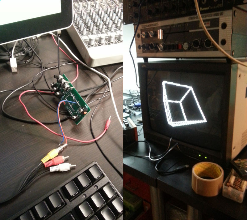
TV Out mod
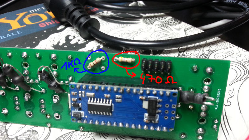
You can mod the Meergranen to generate a black and white composite signal. For this mod you need:
- 1 KΩ resistor
- 470 Ω resistor
- some wires
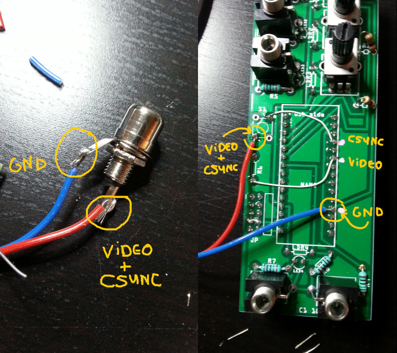
- a RCA/cinch male or female connector, you can change it later, here we use female because it will be use to mount the socket on the panel (eventually)
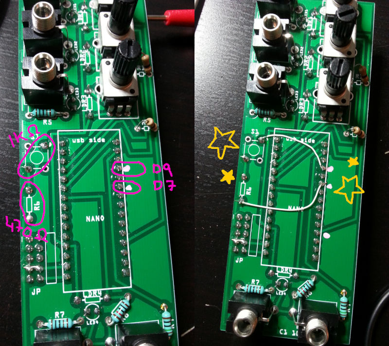
- a meergranen board that does not have the trigger button yet, because we'll make use of some of its tracks and holes.
- faith
- First we put the resistors in place
- Then you solder the legs and trim them
- Notice that we do not need to join the two resistors like on the diagram, because the PCB is already giving us a track that does exactly this
- Take note of pins D7 and D9, they need to be connected to the resistors 470 Ω and 1 KΩ respectively.
- Finally connect your video cable, on RCA the ground is always the outer part and the signal the inner part of the plug.
- done!
Adding a Volume control knob to the Meergranen
Adding a simple volume control knob to the Meergranen module:
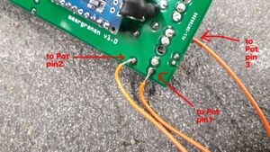
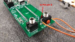
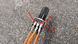
- Remove resistor R9 (150ohm). Just cut it away. Then:
Just solder 3 wires from these points to corresponding points of the potmeter.
- Ask Mark if you need any help!
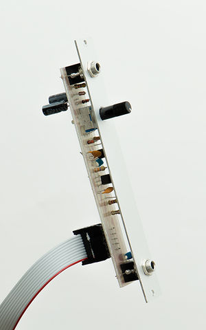
Modules - Low frequency oscillator
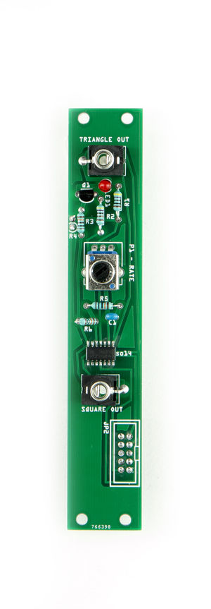
Analog lfo frequency oscillator, delivers waves below the speed of sound. Usefull for triggering other things (beats, filters, etc). Based on quad-opamp, can deliver up to 2x square wave + 2x triangle wave. In this configuration/pcb only 1x square + 1x triangle. Speed of oscillation depening on potentiometer.
Build Instructions
Building this module is a soft introduction into the world of electronics where humans cannot handle, build, or see the components they are using. Introducing: Surface Mount Devices > SDM (or surface mount technology > SMT). In contrast to 'through hole type' components, these smd parts don't need drilling at all, efficient! Not designed to be handled by humans, but for space saving and efficiency, you can still try!
Use the BOM (Bill Of Materials) to see what components you need. This time we introduce IC's, Transistors and IDC connectors. They all have a specific orientation. The white silkscreen on the PCB hints at this, but sometimes its hard to see (LED +, long leg goes into square hole) or drawn incorrectly:
BUG: The white silkscreen of the IDC connector (marked 'JP2') is wrong, Refer to the example how it should be (hint, 180deg turn).
Soldering SMD
-put a little bit of solder on 1 pad of the pcb
-check the orientation of the IC (Integrated Circuit, the SMD component)
-CHECK AGAIN WHERE PIN 1 SHOULD GO!
-place smd ic correctly on the pads, keep in place with finger
-touch the leg that corresponds with the pad containing some solder
-let the solder melt, and remove the soldering iron
-now the ic is fixed in place!
-check the orientation again, now is the time to make corrections (when all pins are soldered its very very hard to remove the IC withouth damaging the board and ic.)
solder the rest of the pins:
-clean your soldering tip (do this for every pin)
-touch the pin+pad with soldering tip, add some solder, remove soldering tip
-repeat.
-the pin spacing is small, dont add too much solder, clean tip after soldering each pin (clean bridges with solder wick).
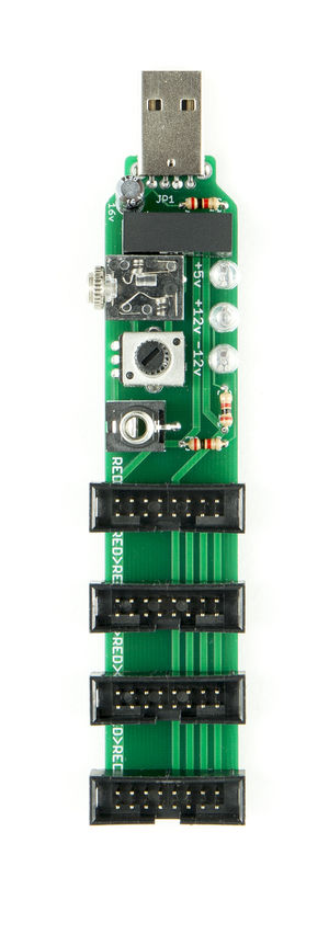
Modules - Power Supply
Use a usb wall wart adaptor or powerbank (laptop WILL die!)
Credits: https://github.com/TomWhitwell/StupidUSBPower
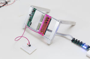
Meergranen powered by Power Supply hooked up to a powerbank.
Up to four Meergranen (or other Eurorack modules) can be powered through this device (max current is aroun 150mA though!).
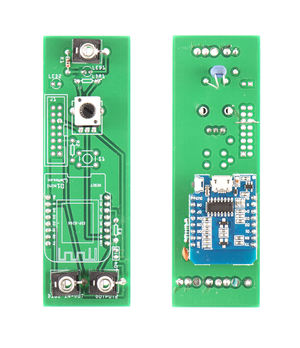
Modules - Wemos D1 Mini/ESP8266wifi
bugs:
- as with meergranen, the ground pin on the power-header needs to be bridged.
- playing samples like the memphis code needs the output through trough pin rx (here its pin...7?)
howto:
Code can be written using the Arduino IDE. First add the library that supports the Wemos D1 Mini board:
https://www.centennialsoftwaresolutions.com/post/arduino-ide-wemos-d1-mini-board-support-install-blink-led-instructions
replace the json url in the guid above with the following tho: https://github.com/esp8266/Arduino/releases/download/2.3.0/package_esp8266com_index.json
Modules - Meergranen v1.1
In the making of the PCB some minor issues creeped up. Luckily circumventable in code:
a0 = a7
a1 = a6
a2 = a5
a3 = a4
The pcb layout is lost due to computer crash...
File:Manual-meergranen1.1-web2.pdf < Manual
Frontpanels
Temporary place for the front panel vector files: http://dennisdebel.nl/downloads/xpub/frontpanels/ (soon on GIT).
Cables
Flat cables with IDC connectors ('eurorack power cables') (Lint- or Bandkabel in Dutch)
Patch cable (mono TS (Tip-Sleeve)3.5mm Male Jacks)
,
Glossary
Patch Cables - mono 3.5 mm male jack-jack cables used to interconnect eurorack modules.
Control Voltage - or CV, a signal used to control synths. typically within the -15 to +15v range (DC or AC).
Breadboard - or solderless-breadboard is a plastic board with interconnected holes for prototyping electronic circuits using jumper cables instead of (semi) permanent solder.
Soldering tin - combination of low melting point metals and resin flux. Sticks to copper, various metals and itself (not to aluminium, stainless steel, plastic, wood etc.)
PCB - Printed Circuit Board - Fiberglass (FR4) coated with copper. Etching away the copper allows for creating traces for electrical circuits. Professionally made boards are silskreened with soldermask (only exposing the places where solder is allowed and protecting the fragile copper traces + lettering for component placement.
Resistor - Slows down electrons, reducing current and thus voltage (Ohms Law, U=IxR) by converting it to heat. Units in Ohms > 1k = 1 kilo Ohm = 1000 Ohm, 0r = 0 Ohm (can be used to bride traces on a PCB)
LED - Light emitting diode, Has polarity: a positive (anode) and negative (cathode) leg. The longest leg is the positive one, keep this in mind when placing the component!
LDR - Light Dependant Resistor, a variable resitor based on light. The more light the lower the resistance and vice versa. Also called light sensor. Units in Ohms
Potentiometer - Rotary or sliding (like on audio mixers) variable resistor. Resistance is changed by turning the knob. Units in Ohms
Ceramic Capacitor - No polarity. Stores enegry until full and then releases it (like a bucket). Can be used for filtering signals (high frequencies will chose to go over a capacitor, low frequencies rather choose to go through a resistor). Units in Farad (pico, nano)
Electrolytic Capacitor - Has polarity. Stores enegry until full and then releases it (like a bucket). (high frequencies will chose to go over a capacitor, low frequencies rather choose to go through a resistor)Units in Farad (mirco, milli)
IC - Integrated Circuit, a single component housing various circuits. Examples: 555 timer, CMOS logic, Opamps,
IDC Connector - Special 'solderless' connectors for ribbon cable, press fit. Use vice, not hammer, be gentle on the brittle material.
Heatshrink - Tube that shrinks when heat is applied (use: lighter, paintstripper, soldering iron), handy for isolating wires, contacts and blocking external light when using LDRS
SMD/SMT - Surface Mount Device/Surface Mount Technology; components that are not soldered through holes, but directly to the PCB
THT - Through Hole Type: components that have long legs that go ...through holes before soldering
Trigger - a control voltage that gives a quick peak, used to trigger drums for example. Typically a harsh square wave.
Gate - a control voltage that follows a (ADSR) slope over time, useful for filters, pitch, notes. Typically a complex wave.
Transistor - Using a plumbing analogy: this is a tap: turn it open with a little effort (current) , allows many electrons to flow. Usable as switch (on off) and thus also to create oscillations (rapid on-off switches).
Ribbon cable - Also called flat cable, multiple parallel conducting wires. (Dutch: lint- or bandkabel)
Vactrols - Vactrols turn voltage into resistance. The 'hotter' the signal, the lower the resistance. Consist of one LED and one LDR, applying voltage to the LED creates light, influencing the resistance of the LDR.
Wire Wrap - before through hole and smd, there was wire wrap, wrap the components legs around a header pin for a airtight solderless, reverseable connection.
Inputs Outputs
Outputs
https://www.facebook.com/HARRYPL0TTER/ Harry Plotter (aka dennis verschoor akak mono-poly, maintainer of worm synth lab), using modular synths to control xy- pen plotters
Shops
Up until a few years ago it was not strange to bike a few minutes to a nearby electronics shop to buy a headphone jack input socket or battery holder. In 2015 the last electronics (component) shop of Rotterdam closed (DIL). Many preceded (2014 Van Der Bend) and many followed, leaving us with just a handful of physical shops to get (unwanted) advice and goods at a premium price without waiting for yellow envelopes from China. Besides not being able to physically examine the goods for sale (will it fit?) more important issues arise. Beyond supporting your local entrepreneur, the decline of DIY shops like the above signify a certain level of consumerism, painfully acknowledging planned obsolesce over DIY repair culture.
Local Shops
Rotterdams Electronica Depot a sporadic electronics shop near you...inquire dennis for more info
https://www.radiotwenthe.nl/ The Hague
https://www.hf-electronics.nl/ Haarlem
https://www.baco-army-goods.nl/ Ijmuiden
http://www.radiopiet.nl/ Arnhem
https://www.tinytronics.nl/ Eindhoven, semi public shop, sells Chinese knock-offs at a premium..
https://www.hobbyelectronica.nl/ Online only, quick delivery, expensive-ish
https://www.kiwi-electronics.nl/ Online only, quick delivery, expensive, recently burned down, sells adafruit stuff etc (expensive-ish)
European Shops
https://www.tme.eu/nl/en/ Member of the Shenzhen (China) Chamber of Commerce. That says everything, please forget box pushers like conrad, farnell, digikey who will rip you off
China
(Almost) EVERYTHING mentioned above comes from Shenzhen, China...so aliexpress.com (or taobao....good luck!). It even pays of to fly to HK, get a SZ port visa and buy what you need in case you want bulk items.
Pads
Reading/Watching/Listening List
http://www.gieskes.nl/ databending circuitboard designs, owns his own pick and place machine, music on tape, vinyl, concrete and what not.
https://www.ciat-lonbarde.net/ taking modular synths in some direction
http://www.gjp.info/ originally radio amateur drummer, applying knowledge of electronics to make incredible noise
http://www.electronicpeasant.com/ discovered by accident, but most 'personal homepages' of early synth enthusiast will publish in this manner
https://www.mengqimusic.com/ friend from Beijing offers some nice interfaces
https://www.errorinstruments.com/ your local eurorack pusher, love bbq in Shenzhen, has infinite energy to make some seriously interesting devices
https://www.muffwiggler.com/forum/index.php the forum where all the action takes (took?) place. Terrible name, terrible place, all the goods you need, though scattered over 90+ forum pages, enjoy!
https://www.facebook.com/HARRYPL0TTER/ Harry Plotter (aka dennis verschoor akak mono-poly, maintainer of worm synth lab), using modular synths to control xy- pen plotters
- https://rwm.macba.cat/en/composingwithprocess_tag Very thorough podcast series about composing with algorithms and different processes. With music samples!
- Cathy Lane & Angus Carlyle: In the Field - A thorough interview book about field recording.
- https://daily.redbullmusicacademy.com/2019/04/pause-tape-production-feature Using the cassette player pause button as the main compositional tool.
- Thomas Patteson: The Time of Roland Kayn's Cybernetic Music http://www.thomaspatteson.com/uploads/7/3/8/8/7388316/the_time_of_roland_kayns_cybernetic_music.pdf - Introduction article to Roland Kayn's cybernetic and highly complex algorithmic compositional process.
- http://www.lespressesdureel.com/EN/ouvrage.php?id=7404 - A catalogue and a collection of essays focusing on Florian Hecker's work, which combines algorithmic composition, sound art, text and installation.
- David Toop: Ocean of Sound https://monoskop.org/images/9/9f/Toop_David_Ocean_of_Sound_Aether_Talk_Ambient_Sound_and_Imaginary_Worlds.pdf
- Rara Avis http://alkualkualkualkualkualkualkualkualkualku.org/pmwiki/pmwiki.php/Main/ALKU99 - Cassette + book about synthesizing birdsong. This overlaps with multiple themes we discussed during the workshop.
Connecting the dots:
- The Thinking Machine (1961) - MIT (video)
- Designing Calm Technology (1995) - Mark Weiser and John Seely Brown (text)
- The Third Meaning of Technical Mediation (small extract from Pandora's Hope 1999) - Bruno Latour (text)
- Bell Labs Innovation Song (2000) - Lucent Technologies (video)
- Microworld with William Shatner (1976) - AT&T (video)
- There is no Software (1995) - Friedrich Kittler (text)
- Reflections on Trusting Trust (1984) - Ken Thompson (text)
- Hyperland (1990) - Douglas Adams (video)
- Do artefacts have politics (1980) - Langdon Winner (text)
- Cinco Midi Organiser (2009) - Tim and Eric Awesome Show, Great Job! (video)
- MakeHuman (2018) - Femke Snelting and Jara Rocha (text)
Pages in category "LFP"
The following 22 pages are in this category, out of 22 total.
E
Media in category "LFP"
The following 170 files are in this category, out of 170 total.
- 20190928 150755 copy.jpg 1,547 × 2,268; 2.43 MB
- 20191022 214700.jpg 2,268 × 1,276; 1.76 MB
- 20191030 140218.jpg 2,268 × 1,276; 1.95 MB
- 20191030 140236.jpg 2,551 × 1,435; 2.06 MB
- 20191030 140315.jpg 1,701 × 957; 1.13 MB
- 20191119 153708.jpg 2,551 × 1,435; 1.98 MB
- 20191205 164856.jpg 1,116 × 1,984; 1.13 MB
- 20191215 144305.jpg 2,268 × 1,276; 1.62 MB
- 20200220 171912.jpg 1,701 × 957; 750 KB
- 7 manual.jpg 800 × 794; 498 KB
- 777.jpg 1,000 × 767; 350 KB
- 7tv.jpg 1,595 × 1,181; 1.15 MB
- Additive synthesis.jpg 650 × 137; 8 KB
- Alien.jpg 720 × 540; 705 KB
- Ardiono.jpg 3,264 × 1,836; 1.52 MB
- Baby-drummer.jpg 720 × 540; 704 KB
- Begena.jpg 266 × 421; 37 KB
- Bibi1.mp3 ; 15 KB
- Bibi2.mp3 ; 27 KB
- Caligo.mp3 ; 52 KB
- Catdogmouse.gif 640 × 400; 451 KB
- Clap&grime.mp3 ; 90 KB
- Clpngmusic.jpg 600 × 308; 81 KB
- Compressor.gif 244 × 140; 1.33 MB
- Dagger.jpg 960 × 714; 227 KB
- Democratic composition.jpg 868 × 1,280; 51 KB
- Digital oscilloscope.gif 400 × 225; 3.1 MB
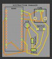
- Distraction manager pcb.JPG 375 × 426; 34 KB
- Dmf air.jpg 1,280 × 960; 143 KB
- Dmf trailer.jpg 1,280 × 960; 70 KB
- Dmf window.jpg 1,280 × 960; 117 KB
- DP1.jpeg 1,800 × 1,200; 533 KB
- DP2.jpeg 1,000 × 667; 637 KB
- Final Glare.jpg 540 × 960; 130 KB
- Fish-bell.jpg 720 × 540; 698 KB
- Fork.jpg 720 × 540; 699 KB
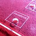
- Frontpanel1.jpg 1,457 × 766; 327 KB
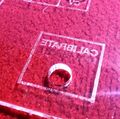
- Frontpanel2.jpg 1,836 × 1,832; 686 KB
- Frontpanel3.jpg 1,836 × 1,814; 836 KB
- Gifcdm.gif 400 × 533; 809 KB
- GLARE Cover 1-03.png 2,150 × 1,071; 39 KB
- Glare PCB.png 850 × 405; 450 KB
- GLARE publish 1.1.jpg 1,754 × 1,754; 366 KB
- GLARE publish 1.12.jpg 1,754 × 1,754; 815 KB
- GLARE sensors01.jpg 5,184 × 3,456; 680 KB
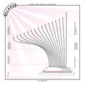
- Glare.png 3,508 × 3,508; 682 KB
- Granular synthscreen.jpg 2,268 × 1,276; 1.64 MB
- Gvrijonmega.jpg 1,134 × 2,016; 550 KB
- Gvrijonnano.jpg 1,134 × 2,016; 447 KB
- Hardwaretimers.jpg 2,408 × 850; 254 KB
- Impaktthursday2.jpg 2,268 × 4,032; 725 KB
- Impaktthursday4.jpg 2,268 × 1,276; 268 KB
- InaudiblePhenomena1.jpg 425 × 756; 136 KB
- InaudiblePhenomena2.jpg 425 × 756; 121 KB
- InaudiblePhenomena3.jpg 756 × 425; 156 KB
- InaudiblePhenomena4.jpg 425 × 756; 189 KB
- Introduction.png 635 × 299; 13 KB
- Kantele.jpg 506 × 144; 24 KB
- Kanteleplayers.jpg 1,024 × 769; 132 KB
- Klebeband.mp3 ; 48 KB
- Knob values.gif 700 × 323; 416 KB
- LDR.jpg 960 × 540; 356 KB
- Ldrarray1.jpg 567 × 1,008; 167 KB
- Ldrarray2.jpg 2,268 × 1,276; 401 KB
- LDRMega.jpg 2,056 × 1,371; 889 KB
- LDRray4.jpg 886 × 591; 620 KB
- LDRray6.jpg 591 × 886; 196 KB
- LFP 15.jpg 4,344 × 2,896; 329 KB
- LFP 18.jpg 5,184 × 3,456; 447 KB
- LFP 19.jpg 4,766 × 3,177; 371 KB
- LFP all 04.jpg 3,059 × 3,030; 956 KB
- LFP bird 12.jpg 3,411 × 5,116; 782 KB
- LFP bird 13.jpg 3,411 × 5,116; 725 KB
- LFP deplayer 02.jpg 1,000 × 667; 310 KB
- LFP deplayer 03 small.jpg 1,000 × 667; 485 KB
- LFP deplayer 06.jpg 1,000 × 667; 295 KB
- LFP deplayer 09.jpg 667 × 1,000; 345 KB
- LFP deplayer 11.jpg 1,000 × 667; 353 KB
- LFP deplayer 12.jpg 886 × 1,329; 969 KB
- LFP deplayer 21.jpg 1,000 × 667; 261 KB
- LFP deplayer 29.jpg 1,000 × 667; 378 KB
- LFP deplayer 30.jpg 1,000 × 1,500; 404 KB
- LFP detail 01.jpg 5,184 × 3,456; 851 KB
- LFP detail 02.jpg 5,184 × 3,456; 652 KB
- LFP detail 03.jpg 5,184 × 3,456; 973 KB
- LFP detail 27 small.jpg 1,800 × 1,200; 640 KB
- LFP detail 28.jpg 5,101 × 3,401; 307 KB
- LFP detail 29.jpg 5,162 × 3,441; 320 KB
- LFP detail 34.jpg 5,184 × 3,456; 904 KB
- LFP detail 35.jpg 5,184 × 3,456; 1,001 KB
- LFPoster1.jpg 1,836 × 3,264; 1,009 KB
- LFPoster2.jpg 3,264 × 1,836; 898 KB
- LFPoster3.jpg 3,264 × 1,836; 846 KB
- LFPoster4.jpg 1,836 × 3,264; 802 KB
- LFPoster5.jpg 1,836 × 3,264; 954 KB
- LFPoster6.jpg 3,264 × 1,836; 756 KB
- Lfpsesh2-code.png 2,110 × 688; 172 KB
- Love-tape.jpg 720 × 540; 695 KB
- Mark - Back.png 1,789 × 1,743; 1.78 MB
- Mark - Front.png 1,789 × 1,753; 1.33 MB
- Max DMF1.jpg 1,836 × 3,264; 1.62 MB
- Max DMF2.jpg 3,264 × 1,836; 2.52 MB
- Max DMF3.jpg 1,836 × 3,264; 2.49 MB
- Max DMF4.jpg 1,836 × 3,264; 2.59 MB
- Max DMF5.gif 480 × 640; 4.01 MB
- Max DMF6.jpg 3,264 × 1,836; 2.29 MB
- Max DMF7.gif 480 × 640; 2.45 MB
- Max DMF8.jpg 3,264 × 1,836; 2.09 MB
- Maxbreadboard1.jpg 2,268 × 1,276; 601 KB
- Maxconceptsketch1.jpg 1,134 × 2,016; 414 KB
- Maxconceptsketch2.jpg 1,134 × 2,016; 396 KB
- Meergranen s.gif 453 × 958; 351 KB
- Meergranen-db.jpg 4,000 × 3,000; 4.07 MB
- Meergranen-samples.png 1,548 × 878; 527 KB
- Meergranen1.jpg 3,264 × 2,448; 1.95 MB
- Meergranen2.jpg 2,448 × 3,264; 2.55 MB
- Meergranen3.jpg 2,448 × 3,264; 2.15 MB
- Mf1.jpeg 480 × 640; 116 KB
- Mf2.jpeg 480 × 640; 134 KB
- Mf3.jpeg 480 × 640; 111 KB
- Modular synth interface.jpg 2,268 × 1,515; 2.37 MB
- Motheremin.jpg 720 × 540; 836 KB
- Multiplexer1.jpg 2,268 × 2,520; 1,010 KB
- Multiplexer2.jpg 2,268 × 1,276; 801 KB
- Musicboxmodule.jpg 2,268 × 1,276; 2.03 MB
- MVDH speech-to-midi-counting.mp3 ; 351 KB
- Mystify understand.jpg 3,264 × 1,836; 2.73 MB
- Olli workshop.jpg 1,280 × 960; 112 KB
- OSC.gif 600 × 338; 1.49 MB
- PCBSchematic.png 1,951 × 923; 89 KB
- Pencil.jpg 720 × 540; 698 KB
- PosterSmallFinal.jpg 1,742 × 2,498; 585 KB
- Publication.gif 200 × 112; 419 KB
- Publication01.jpg 1,000 × 667; 286 KB
- Raspberry-p-3-bird.jpg 726 × 498; 249 KB
- S-Water.mp3 ; 843 KB
- S-Wood.mp3 ; 1.1 MB
- Screen Shot 2019-12-02 at 22.20.11.png 170 × 390; 14 KB
- Sensor plug.jpg 1,390 × 2,472; 675 KB
- Sensor synth.jpg 1,836 × 3,264; 856 KB
- Sensor.png 265 × 893; 10 KB
- SensorProto.jpg 1,836 × 3,264; 836 KB
- SensorTV.jpg 1,836 × 3,264; 669 KB
- Serial plotter.mp4 ; 2.47 MB
- Sess3 2.gif 480 × 640; 1.39 MB
- Sess3 5.jpg 1,836 × 3,264; 1.51 MB
- Sine.mp3 ; 48 KB
- Sine2.mp3 ; 119 KB
- Speech-instrument.jpg 1,417 × 823; 592 KB
- Stapletrigger2.jpg 3,264 × 1,836; 1.56 MB
- Stapletrigger3.jpg 1,836 × 3,264; 1.7 MB
- Stapletrigger4.jpg 3,264 × 1,836; 1.15 MB
- Subtractive-synthesis.png 830 × 299; 21 KB
- Super-in-low.jpg 720 × 540; 727 KB
- Svarog3.jpg 720 × 540; 698 KB
- Take time.jpg 960 × 1,280; 266 KB
- Teensy1.jpg 1,827 × 1,218; 877 KB
- Teensy2.jpg 1,224 × 700; 506 KB
- Testkeyboard1.jpg 2,268 × 1,276; 500 KB
- Tisa take time.mp3 ; 6 MB
- WorkshopOlli1.jpg 2,448 × 3,264; 2.17 MB
- WorkshopOlli2.jpg 3,264 × 2,448; 2.27 MB
- WorkshopOlli4.jpg 3,264 × 2,448; 2.19 MB
- WorkshopOlli5.jpg 3,264 × 2,448; 2.24 MB
- WorkshopOlli7.jpg 1,366 × 1,024; 325 KB
- XPUB - DE PLAYER - INPUT-OUTPUT176-12 december 2019.jpg 1,800 × 1,200; 559 KB
- XPUB - DE PLAYER - INPUT-OUTPUT292-12 december 2019.jpg 1,800 × 1,200; 563 KB
- XPUB - DE PLAYER - INPUT-OUTPUT300-12 december 2019.jpg 1,800 × 1,200; 614 KB
- XPUB - DE PLAYER - INPUT-OUTPUT43-12 december 2019.jpg 1,800 × 1,200; 610 KB
- XPUB workshop.jpg 4,128 × 2,322; 2.75 MB
