Microcontroller 101: Difference between revisions
(Created page with "<pre style="font-weight: bold"> ḿ̬̏ͤͅỉ͔͖̜͌c͕͗ͤ̕̕r̴̨̦͕̝o̯̱̊͊͢c͕͗ͤ̕̕o̯̱̊͊͢ṇ̤͛̒̍t̲̂̓ͩ̑r̴̨̦͕̝o̯̱̊͊͢l̙͖̑̾ͣl̙͖̑̾ͣẹ̿͋̒̕r̴̨̦͕̝ 1̨̹̦͍̀0̗̜͕̅̃1̨̹̦͍̀ </pre> =2022-09-08= * WH.02.125 (Prototyping Space IAS) 9:00 - 16:00 ==Introduction== ===1. Circuit bending=== ===2. Introduction Arduino=== ====Hello World!==== <pre> void s...") |
|||
| (85 intermediate revisions by 3 users not shown) | |||
| Line 5: | Line 5: | ||
</pre> | </pre> | ||
= | =09-04-24 e͎l͎e͎c͎t͎r͎i͎c͎ t͎r͎i͎c͎k͎s͎= | ||
== | ==LOLIN 32 Installation party :~)== | ||
=== | |||
[[File:Lolin32.jpeg|200px|thumb|left|Wemos LOLIN32 - ESP32]] | |||
[[File:D32 pro v2.0.0 3 16x9.jpg|600px|thumb|center|Pinout LOLIN D32 PRO]] | |||
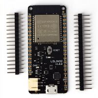
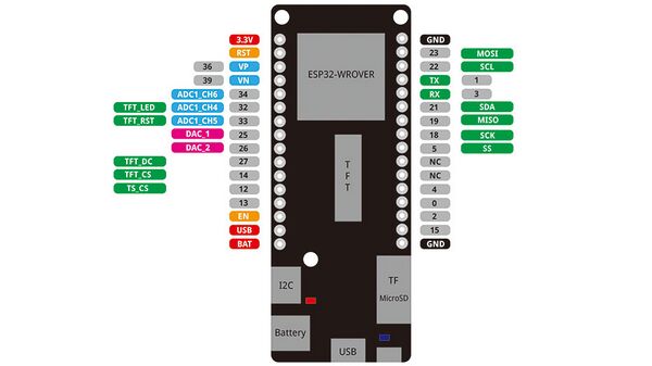
more info about the lolin32 is here: https://www.wemos.cc/en/latest/d32/d32_pro.html | |||
step 1: download [https://www.arduino.cc/en/software Arduino] software | |||
step 2: download [https://www.silabs.com/developers/usb-to-uart-bridge-vcp-drivers?tab=downloads driver] for microcontroller | |||
step 3: install driver | |||
_windows: open Device Manager >> find UART device >> right click and update driver >> select driver | |||
step 4: install esp32 library in the board manager | |||
==Arduino code== | |||
===Hello World!=== | |||
in the Arduino program, select the correct board (WEMOS LOLIN32) and select the USB port you are using | |||
(if you are unsure, check the listed ports, unplug and see what changed) | |||
<pre> | <pre> | ||
void setup() { | void setup() { | ||
Serial.begin(115200); | |||
} | } | ||
| Line 20: | Line 40: | ||
} | } | ||
</pre> | </pre> | ||
[[File:Led | open the Serial Monitor in your arduino IDE and set it to 115200, the baudrate that has been set in the setup function, to see the printed messages. | ||
=== Simple Led blink example === | |||
[[File:LEDBLINK.png|thumb|center|Simple Led Blink Example]] | |||
[[File:LEDBLINKschematics.png|thumb|center|Simple Led Blink Example Schematics]] | |||
<pre> | <pre> | ||
int ledPin = | |||
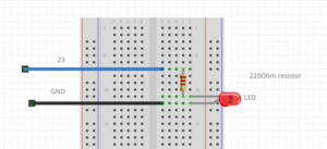
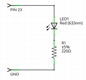
// always use a "preresistor" with the LED, because the 5v coming from the microcontroller is too much | |||
// a LED only consumes ~2.5 volt, the resistor the other volt | |||
// | |||
int ledPin = 23; //the int ledPin is 13 | |||
void setup() { | void setup() { | ||
| Line 37: | Line 66: | ||
} | } | ||
</pre> | </pre> | ||
=== Traffic light example === | |||
[[File: | |||
[[File:Trafficjam.png|thumb|center]] | |||
[[File:Trafficjamschematics.png|thumb|center]] | |||
<pre> | <pre> | ||
int RedLedPin = | int RedLedPin = 23; //the int RedLedPin is 13 | ||
int GreenLedPin = | int GreenLedPin = 22; //the int GreenLedPin is 12 | ||
void setup() { | void setup() { | ||
| Line 64: | Line 96: | ||
} | } | ||
</pre> | </pre> | ||
=== | |||
[[File: | === LDR example === | ||
example with a light resistor. | |||
keep in mind the LDR pin needs to be a pin with a ADC(analog to digital converter), because you check the analog voltage. on the arduino these are the ANALOG IN pins. on the ESP32 the pins with the ADC(check the pinout graphic) | |||
[[File:LDR example.png|thumb|center]] | |||
[[File:LDRschematics.png|thumb|center]] | |||
<pre> | <pre> | ||
int | int LDR = 34; //the LDR pin | ||
void setup() { | void setup() { | ||
pinMode( | Serial.begin(115200); | ||
pinMode(LDR,INPUT); //LDR is an INPUT | |||
} | } | ||
void loop() { | void loop() { | ||
int value = analogRead(LDR); // read the analog value of the LDR | |||
Serial.println(value); // print the value of the LDR, open serial monitor | |||
delay(10); | |||
} | } | ||
</pre> | </pre> | ||
=== | |||
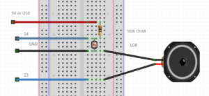
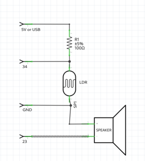
[[File: | === LDR & speaker example === | ||
[[File:Ldrspeaker.png|thumb|center]] | |||
[[File:Ldrspeakerschematics.png|thumb|center]] | |||
<pre> | <pre> | ||
int LDR = 34; //the LDR pin | |||
int | int speaker = 23; | ||
void setup() { | void setup() { | ||
Serial.begin(115200); | Serial.begin(115200); | ||
pinMode( | pinMode(LDR,INPUT); //LDR is an INPUT | ||
pinMode( | pinMode(speaker,OUTPUT); //speaker is a OUTPUT | ||
} | } | ||
void loop() { | void loop() { | ||
int value = analogRead(LDR); // read the analog value of the LDR | |||
Serial.println(value); // print the value of the LDR, open serial monitor | |||
tone(speaker,value); //create a frequency on the speaker pin; the frequency hertz is the value | |||
delay(10); | |||
} | } | ||
</pre> | </pre> | ||
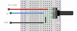
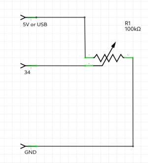
= | === Poti example === | ||
[[File:Poti.png|thumb|center]] | |||
== | [[File:Potischematics.png|thumb|center]] | ||
[[File: | |||
<pre> | <pre> | ||
int poti = 34; //the poti pin | |||
void setup() { | |||
void setup(){ | Serial.begin(115200); | ||
pinMode(poti,INPUT); //poti is an INPUT | |||
} | } | ||
void loop(){ | |||
void loop() { | |||
Serial.println( | int value = analogRead(poti); // read the analog value of the poti | ||
Serial.println(value); // print the value of the poti, open serial monitor | |||
delay(10); | delay(10); | ||
} | } | ||
</pre> | </pre> | ||
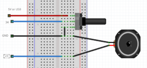
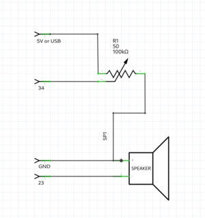
== | === Poti & speaker example === | ||
[[File:Potispeaker.png|thumb|center]] | |||
[[File:Potispeakerschematics.png|thumb|center]] | |||
<pre> | <pre> | ||
//keep in mind you can only use a mini speaker. for bigger speakers you need an amplifier. | |||
int poti = 34; //the pto pin | |||
int speaker = 23; | |||
void setup() { | |||
Serial.begin(115200); | |||
pinMode(poti,INPUT); //poti is an INPUT | |||
pinMode(speaker,OUTPUT); //speaker is a OUTPUT | |||
} | |||
void loop() { | |||
int value = analogRead(poti); // read the analog value of the poti | |||
Serial.println(value); // print the value of the poti, open serial monitor | |||
tone(speaker,value); //create a frequency on the speaker pin; the frequency hertz is the value | |||
delay(10); | |||
} | |||
</pre> | |||
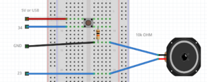
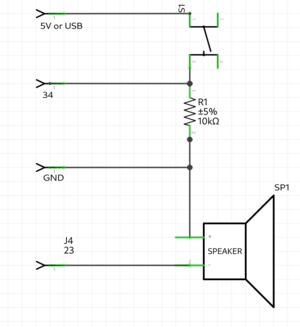
int | === Button & alarm example === | ||
[[File:Buttonspeaker.png|thumb|center]] | |||
[[File:Buttonschematics.png|thumb|center]] | |||
<pre> | |||
int button = 34; | |||
int speaker = 23; | |||
void setup() { | |||
Serial.begin(115200); //make usb connection | |||
pinMode(button, INPUT); //button is an INPUT | |||
pinMode(speaker, OUTPUT); //speaker is an OUTPUT | |||
} | } | ||
void loop(){ | |||
void loop() { | |||
bool value = digitalRead(button); //read the digital value of button | |||
if(button){ | |||
Serial.println("start alarm"); | |||
for(int repeter = 0; repeter<5; repeter++){ //repeat 5 times | |||
for(int frequency = 500; frequency<1200; frequency++){ //count from 500 to 1200 | |||
tone(speaker, fequency); //generate the frequency on the speaker pin | |||
Serial.println( | delay(5); | ||
} | |||
notone(speaker); //turn off the speaker pin | |||
delay(500); // | |||
} | |||
}else{ | |||
Serial.println("button not pressed"); | |||
} | |||
} | } | ||
</pre> | </pre> | ||
== | =16-04-24 ๓໐t໐rŞ + ŞēຖŞ໐rŞ = r໐๖໐t= | ||
==sensors== | |||
===humidity=== | |||
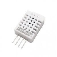
[[File:Dht22.jpg|200px]] | |||
the DHT22 humidity sensor :) | |||
<pre> | <pre> | ||
#include < | #include <DHT.h>; | ||
//Constants | |||
#define DHTPIN 21 // what pin we're connected to | |||
#define DHTTYPE DHT22 // DHT 22 (AM2302) | |||
DHT dht(DHTPIN, DHTTYPE); //// Initialize DHT sensor for normal 16mhz Arduino | |||
int | //Variables | ||
int chk; | |||
float hum; //Stores humidity value | |||
float temp; //Stores temperature value | |||
void setup() | |||
{ | |||
Serial.begin(9600); | |||
dht.begin(); | |||
} | } | ||
void loop(){ | |||
void loop() | |||
{ | |||
Serial. | //Read data and store it to variables hum and temp | ||
hum = dht.readHumidity(); | |||
temp= dht.readTemperature(); | |||
//Print temp and humidity values to serial monitor | |||
Serial.print("Humidity: "); | |||
Serial.print(hum); | |||
Serial.print(" %, Temp: "); | |||
Serial.print(temp); | |||
Serial.println(" Celsius"); | |||
delay(2000); //Delay 2 sec. | |||
} | } | ||
</pre> | </pre> | ||
== | ===sound=== | ||
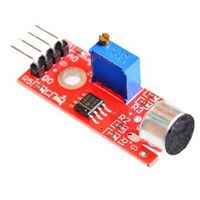
[[File:Sound sensorky.jpg|200px]] | |||
KY-037 Sound Detection Sensor Module :::;;-)) | |||
<pre> | <pre> | ||
// | int sensorPin = 21; // select the input pin for the potentiometer a0 on board, D1 pinout not connected | ||
int sensorValue = 0; // variable to store the value coming from the sensor | |||
// | |||
void setup() { | void setup() { | ||
Serial.begin( | // declare the ledPin as an OUTPUT: | ||
Serial.begin(9600); | |||
pinMode(22, OUTPUT); // | |||
} | } | ||
void loop() { | void loop() { | ||
// read the value from the sensor: | |||
sensorValue = analogRead(sensorPin); | |||
Serial.println( | // turn the ledPin on | ||
delay( | Serial.println(sensorValue); | ||
if (sensorValue>448) { | |||
Serial.println("high detected"); | |||
digitalWrite(22, HIGH); | |||
Serial.println("Blink On"); | |||
delay(2000); | |||
digitalWrite(22, LOW); | |||
} | } | ||
else { | |||
digitalWrite(22, LOW); | |||
} | } | ||
} | } | ||
</pre> | </pre> | ||
== | ===soil moisture=== | ||
[[File:Soil moisture sensor.jpg|200px]] | |||
Capacitive Soil Moisture Sensor Module :~) | |||
<pre> | <pre> | ||
const int dry = 595; // Value for dry sensor | |||
const int wet = 239; // Value for wet sensor | |||
void setup() { | void setup() { | ||
Serial.begin( | Serial.begin(9600); // Initialize serial communication | ||
} | } | ||
void loop() { | void loop() { | ||
int sensorVal = analogRead(26); // Read moisture sensor value from pin A0 | |||
int percentageHumidity = map(sensorVal, wet, dry, 0, 100); // Convert sensor value to percentage | |||
Serial.print(percentageHumidity); // Print percentage humidity value | |||
Serial.println("%"); // Print % symbol | |||
delay(100); // Delay for stability | |||
} | } | ||
</pre> | |||
===sonar distance=== | |||
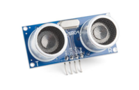
[[File:Sonar sensor.png|200px]] | |||
<pre> | |||
*/ | |||
// defines pins numbers | |||
const int trigPin = 21; | |||
const int echoPin = 14; | |||
// defines variables | |||
long duration; | |||
int distance; | |||
void setup() { | |||
pinMode(trigPin, OUTPUT); // Sets the trigPin as an Output | |||
pinMode(echoPin, INPUT); // Sets the echoPin as an Input | |||
Serial.begin(9600); // Starts the serial communication | |||
} | } | ||
void loop() { | |||
void | // Clears the trigPin | ||
// | digitalWrite(trigPin, LOW); | ||
for( | delayMicroseconds(2); | ||
// Sets the trigPin on HIGH state for 10 micro seconds | |||
digitalWrite(trigPin, HIGH); | |||
delayMicroseconds(10); | |||
digitalWrite(trigPin, LOW); | |||
// Reads the echoPin, returns the sound wave travel time in microseconds | |||
duration = pulseIn(echoPin, HIGH); | |||
// Calculating the distance | |||
distance = duration * 0.034 / 2; | |||
// Prints the distance on the Serial Monitor | |||
Serial.print("Distance: "); | |||
Serial.println(distance); | |||
} | } | ||
</pre> | </pre> | ||
== | ===water sensor=== | ||
[[File:Water sensor.JPG|200px]] | |||
https://lastminuteengineers.com/water-level-sensor-arduino-tutorial/ | |||
<pre> | <pre> | ||
// | // Sensor pins | ||
#define sensorPower 7 | |||
#define sensorPin A0 | |||
# | |||
// Value for storing water level | |||
int val = 0; | |||
void setup() { | void setup() { | ||
// Set D7 as an OUTPUT | |||
pinMode(sensorPower, OUTPUT); | |||
// Set to LOW so no power flows through the sensor | |||
digitalWrite(sensorPower, LOW); | |||
Serial.begin(9600); | |||
} | } | ||
void loop() { | void loop() { | ||
//get the reading from the function below and print it | |||
int level = readSensor(); | |||
Serial.print("Water level: "); | |||
Serial.println(level); | |||
delay(1000); | |||
} | } | ||
//This is a function used to get the reading | |||
int readSensor() { | |||
digitalWrite(sensorPower, HIGH); // Turn the sensor ON | |||
delay(10); // wait 10 milliseconds | |||
val = analogRead(sensorPin); // Read the analog value form sensor | |||
digitalWrite(sensorPower, LOW); // Turn the sensor OFF | |||
return val; // send current reading | |||
} | } | ||
</pre> | |||
==sensor readings as motor control== | |||
to merge, the poti value needs to be replaced with the new sensor value, and the map max value adjusted | |||
DHT merge: | |||
<pre> | <pre> | ||
#include <DHT.h>; | |||
#include <ESP32Servo.h> //this | |||
#include < | |||
Servo | Servo twister; //this | ||
//Constants | |||
#define DHTPIN 21 // what pin we're connected to | |||
#define DHTTYPE DHT22 // DHT 22 (AM2302) | |||
DHT dht(DHTPIN, DHTTYPE); //// Initialize DHT sensor for normal 16mhz Arduino | |||
void setup() { | |||
//Variables | |||
int chk; | |||
float hum; //Stores humidity value | |||
float temp; //Stores temperature value | |||
void setup() | |||
{ | |||
Serial.begin(9600); | |||
dht.begin(); | |||
twister.attach(25); //this | |||
} | } | ||
void loop() { | void loop() | ||
{ | |||
//Read data and store it to variables hum and temp | |||
hum = dht.readHumidity(); | |||
temp= dht.readTemperature(); | |||
//Print temp and humidity values to serial monitor | |||
Serial.print("Humidity: "); | |||
Serial.print(hum); | |||
Serial.print(" %, Temp: "); | |||
Serial.print(temp); | |||
Serial.println(" Celsius"); | |||
delay(2000); //Delay 2 sec. | |||
int degree = map(temp, 0, 36, 0, 180); //this, update temp with your value | |||
twister.write(degree); | |||
} | } | ||
</pre> | </pre> | ||
= | =23-04-24 l͓̽i͓̽n͓̽k͓̽i͓̽n͓̽g͓̽ t͓̽h͓̽e͓̽ r͓̽e͓̽a͓̽l͓̽m͓̽s͓̽= | ||
https://github.com/espressif/arduino-esp32/blob/master/libraries/WiFi/examples/WiFiAccessPoint/WiFiAccessPoint.ino | |||
Using the ESP32 to create a hotspot and serve a simple webpage on http://192.168.4.1/ when connected. | |||
<pre> | <pre> | ||
/ | /* | ||
WiFiAccessPoint.ino creates a WiFi access point and provides a web server on it. | |||
Steps: | |||
1. Connect to the access point "yourAp" | |||
2. Point your web browser to http://192.168.4.1/H to turn the LED on or http://192.168.4.1/L to turn it off | |||
OR | |||
Run raw TCP "GET /H" and "GET /L" on PuTTY terminal with 192.168.4.1 as IP address and 80 as port | |||
Created for arduino-esp32 on 04 July, 2018 | |||
by Elochukwu Ifediora (fedy0) | |||
*/ | |||
#include <WiFi.h> | |||
#include <WiFiClient.h> | |||
#include <WiFiAP.h> | |||
#define LED_BUILTIN 23 // Set the GPIO pin where you connected your test LED or comment this line out if your dev board has a built-in LED | |||
// Set these to your desired credentials. | |||
const char *ssid = "joseph"; | |||
const char *password = "knierzinger"; | |||
// | |||
WiFiServer server(80); | |||
void setup() { | void setup() { | ||
Serial.begin(115200); | pinMode(LED_BUILTIN, OUTPUT); | ||
Serial.begin(115200); | |||
Serial.println(); | |||
Serial.println("Configuring access point..."); | |||
// You can remove the password parameter if you want the AP to be open. | |||
// a valid password must have more than 7 characters | |||
if (!WiFi.softAP(ssid, password)) { | |||
log_e("Soft AP creation failed."); | |||
while(1); | |||
} | |||
IPAddress myIP = WiFi.softAPIP(); | |||
Serial.print("AP IP address: "); | |||
Serial.println(myIP); | |||
server.begin(); | |||
Serial.println("Server started"); | |||
} | } | ||
void loop() { | |||
WiFiClient client = server.available(); // listen for incoming clients | |||
int sensorValue = analogRead(34); | |||
if (client) { // if you get a client, | |||
Serial.println("New Client."); // print a message out the serial port | |||
String currentLine = ""; // make a String to hold incoming data from the client | |||
while (client.connected()) { // loop while the client's connected | |||
if (client.available()) { // if there's bytes to read from the client, | |||
char c = client.read(); // read a byte, then | |||
Serial.write(c); // print it out the serial monitor | |||
if (c == '\n') { // if the byte is a newline character | |||
// if the current line is blank, you got two newline characters in a row. | |||
// that's the end of the client HTTP request, so send a response: | |||
if (currentLine.length() == 0) { | |||
// HTTP headers always start with a response code (e.g. HTTP/1.1 200 OK) | |||
// and a content-type so the client knows what's coming, then a blank line: | |||
client.println("HTTP/1.1 200 OK"); | |||
client.println("Content-type:text/html"); | |||
client.println(); | |||
// the content of the HTTP response follows the header: | |||
client.print("<meta http-equiv='refresh' content='0.1'>"); | |||
client.print("<style>body{background-color:red;}</style><br>"); | |||
int objectValue = map(sensorValue, 0, 4096, 0, 200); | |||
client.print("<style>.object{background-color:black;}</style><br>"); | |||
client.print("<style>.object{width: 400px;height:400px;}</style><br>"); | |||
client.print("<style>.object{border-radius:"+String(objectValue)+"px; }</style><br>"); | |||
client.print("<h1>eviltwin data " + String(sensorValue) + "</h1><br>"); | |||
client.print("<div class='object'></div><br>"); | |||
client.print("Click <a href=\"/H\">here</a> to turn ON the LED.<br>"); | |||
client.print("Click <a href=\"/L\">here</a> to turn OFF the LED.<br>"); | |||
// The HTTP response ends with another blank line: | |||
client.println(); | |||
// break out of the while loop: | |||
break; | |||
} else { // if you got a newline, then clear currentLine: | |||
currentLine = ""; | |||
} | |||
} else if (c != '\r') { // if you got anything else but a carriage return character, | |||
currentLine += c; // add it to the end of the currentLine | |||
} | |||
// Check to see if the client request was "GET /H" or "GET /L": | |||
if (currentLine.endsWith("GET /H")) { | |||
digitalWrite(LED_BUILTIN, HIGH); // GET /H turns the LED on | |||
} | |||
if (currentLine.endsWith("GET /L")) { | |||
digitalWrite(LED_BUILTIN, LOW); // GET /L turns the LED off | |||
} | |||
} | |||
} | |||
// close the connection: | |||
client.stop(); | |||
Serial.println("Client Disconnected."); | |||
} | |||
} | } | ||
</pre> | |||
Latest revision as of 13:14, 3 July 2024
ḿ̬̏ͤͅỉ͔͖̜͌c͕͗ͤ̕̕r̴̨̦͕̝o̯̱̊͊͢c͕͗ͤ̕̕o̯̱̊͊͢ṇ̤͛̒̍t̲̂̓ͩ̑r̴̨̦͕̝o̯̱̊͊͢l̙͖̑̾ͣl̙͖̑̾ͣẹ̿͋̒̕r̴̨̦͕̝ 1̨̹̦͍̀0̗̜͕̅̃1̨̹̦͍̀
09-04-24 e͎l͎e͎c͎t͎r͎i͎c͎ t͎r͎i͎c͎k͎s͎
LOLIN 32 Installation party :~)
more info about the lolin32 is here: https://www.wemos.cc/en/latest/d32/d32_pro.html
step 1: download Arduino software
step 2: download driver for microcontroller
step 3: install driver
_windows: open Device Manager >> find UART device >> right click and update driver >> select driver
step 4: install esp32 library in the board manager
Arduino code
Hello World!
in the Arduino program, select the correct board (WEMOS LOLIN32) and select the USB port you are using (if you are unsure, check the listed ports, unplug and see what changed)
void setup() {
  Serial.begin(115200);
}

void loop() {
  Serial.println("Hello World!");   //sends a message to the computer
}
open the Serial Monitor in your arduino IDE and set it to 115200, the baudrate that has been set in the setup function, to see the printed messages.
Simple Led blink example
// always use a "preresistor" with the LED, because the 5v coming from the microcontroller is too much
// a LED only consumes ~2.5 volt, the resistor the other volt
//

int ledPin = 23;               //the int ledPin is 13

void setup() {
  pinMode(ledPin,OUTPUT);      //ledPin is a OUTPUT
}

void loop() {
  digitalWrite(ledPin,HIGH);   //turns pin 13 on
  delay(500);                  //stops the loop for 500 milliseconds
  digitalWrite(ledPin,LOW);    //turns pin 13 off
  delay(500);                  //stops the loop for 500 milliseconds
}
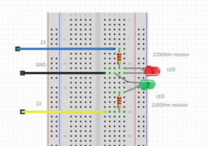
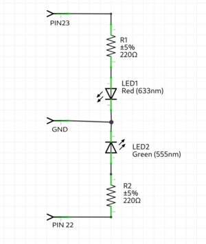
Traffic light example
int RedLedPin = 23;                 //the int RedLedPin is 13
int GreenLedPin = 22;               //the int GreenLedPin is 12

void setup() {
  pinMode(RedLedPin,OUTPUT);        //ledPin is a OUTPUT
  pinMode(GreenLedPin,OUTPUT);      //ledPin is a OUTPUT

}

void loop() {
  digitalWrite(GreenLedPin,HIGH);   //turns green led  on
  delay(5000);                      //stops the loop for 5000 milliseconds
  for(int i = 0; i < 5; i++){       //this for loop gets 5 times repeated
    digitalWrite(GreenLedPin,LOW);  //turns green led off
    delay(500);                     //stops the loop for 500 milliseconds
    digitalWrite(GreenLedPin,HIGH); //turns green led off
    delay(500);                     //stops the loop for 500 milliseconds
  }
  digitalWrite(GreenLedPin,LOW);    //turns green led off
  digitalWrite(RedLedPin,HIGH);     //turns red led on
  delay(5000);                      //stops the loop for 5000 milliseconds
  digitalWrite(RedLedPin,LOW);      //turns red led on
}
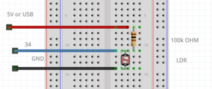
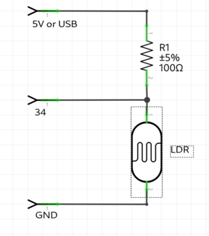
LDR example
example with a light resistor. keep in mind the LDR pin needs to be a pin with a ADC(analog to digital converter), because you check the analog voltage. on the arduino these are the ANALOG IN pins. on the ESP32 the pins with the ADC(check the pinout graphic)
int LDR = 34;                 //the LDR pin

void setup() {
  Serial.begin(115200);
  pinMode(LDR,INPUT);        //LDR is an INPUT
}

void loop() {
  int value = analogRead(LDR); // read the analog value of the LDR
  Serial.println(value);       // print the value of the LDR, open serial monitor
  delay(10);
}
LDR & speaker example
int LDR = 34;                 //the LDR pin
int speaker = 23;

void setup() {
  Serial.begin(115200);
  pinMode(LDR,INPUT);        //LDR is an INPUT
  pinMode(speaker,OUTPUT);        //speaker is a OUTPUT
}

void loop() {
  int value = analogRead(LDR); // read the analog value of the LDR
  Serial.println(value);       // print the value of the LDR, open serial monitor
  tone(speaker,value);         //create a frequency on the speaker pin; the frequency hertz is the value
  delay(10);
}
Poti example
int poti = 34;                 //the poti pin

void setup() {
  Serial.begin(115200);
  pinMode(poti,INPUT);        //poti is an INPUT
}

void loop() {
  int value = analogRead(poti); // read the analog value of the poti
  Serial.println(value);       // print the value of the poti, open serial monitor
  delay(10);
}
Poti & speaker example
//keep in mind you can only use a mini speaker. for bigger speakers you need an amplifier.
int poti = 34;                 //the pto pin
int speaker = 23;

void setup() {
  Serial.begin(115200);
  pinMode(poti,INPUT);        //poti is an INPUT
  pinMode(speaker,OUTPUT);        //speaker is a OUTPUT
}

void loop() {
  int value = analogRead(poti); // read the analog value of the poti
  Serial.println(value);       // print the value of the poti, open serial monitor
  tone(speaker,value);         //create a frequency on the speaker pin; the frequency hertz is the value
  delay(10);
}
Button & alarm example
int button = 34;
int speaker = 23;

void setup() {
  Serial.begin(115200);   //make usb connection
  pinMode(button, INPUT);    //button is an INPUT
  pinMode(speaker, OUTPUT);    //speaker is an OUTPUT

}

void loop() {
  bool value = digitalRead(button);    //read the digital value of button
  if(button){
    Serial.println("start alarm");
    for(int repeter = 0; repeter<5; repeter++){   //repeat 5 times
      for(int frequency = 500; frequency<1200; frequency++){    //count from 500 to 1200
        tone(speaker, fequency);    //generate the frequency on the speaker pin
        delay(5);
      }
      notone(speaker);    //turn off the speaker pin
      delay(500);         //
    }
  }else{
    Serial.println("button not pressed");
  }
}
16-04-24 ๓໐t໐rŞ + ŞēຖŞ໐rŞ = r໐๖໐t
sensors
humidity
#include <DHT.h>;

//Constants
#define DHTPIN 21     // what pin we're connected to
#define DHTTYPE DHT22   // DHT 22  (AM2302)
DHT dht(DHTPIN, DHTTYPE); //// Initialize DHT sensor for normal 16mhz Arduino


//Variables
int chk;
float hum;  //Stores humidity value
float temp; //Stores temperature value

void setup()
{
    Serial.begin(9600);
	dht.begin();

}

void loop()
{
    //Read data and store it to variables hum and temp
    hum = dht.readHumidity();
    temp= dht.readTemperature();
    //Print temp and humidity values to serial monitor
    Serial.print("Humidity: ");
    Serial.print(hum);
    Serial.print(" %, Temp: ");
    Serial.print(temp);
    Serial.println(" Celsius");
    delay(2000); //Delay 2 sec.
}
sound
KY-037 Sound Detection Sensor Module :::;;-))
int sensorPin = 21;    // select the input pin for the potentiometer a0 on board, D1 pinout not connected
int sensorValue = 0;  // variable to store the value coming from the sensor


void setup() {
  // declare the ledPin as an OUTPUT:
  Serial.begin(9600);
  pinMode(22, OUTPUT); //
}


void loop() {
  // read the value from the sensor:
  sensorValue = analogRead(sensorPin);
  // turn the ledPin on
  Serial.println(sensorValue);


  if (sensorValue>448) {
    Serial.println("high detected");
    digitalWrite(22, HIGH);
    Serial.println("Blink On");
    delay(2000);
    digitalWrite(22, LOW);

  }
  else {
    digitalWrite(22, LOW);
  }
}
soil moisture
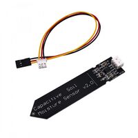 Capacitive Soil Moisture Sensor Module :~)
const int dry = 595; // Value for dry sensor
const int wet = 239; // Value for wet sensor

void setup() {
  Serial.begin(9600); // Initialize serial communication
}

void loop() {
  int sensorVal = analogRead(26); // Read moisture sensor value from pin A0

  int percentageHumidity = map(sensorVal, wet, dry, 0, 100); // Convert sensor value to percentage

  Serial.print(percentageHumidity); // Print percentage humidity value
  Serial.println("%"); // Print % symbol
  delay(100); // Delay for stability
}
sonar distance
*/
// defines pins numbers
const int trigPin = 21;
const int echoPin = 14;
// defines variables
long duration;
int distance;
void setup() {
  pinMode(trigPin, OUTPUT); // Sets the trigPin as an Output
  pinMode(echoPin, INPUT); // Sets the echoPin as an Input
  Serial.begin(9600); // Starts the serial communication
}
void loop() {
  // Clears the trigPin
  digitalWrite(trigPin, LOW);
  delayMicroseconds(2);
  // Sets the trigPin on HIGH state for 10 micro seconds
  digitalWrite(trigPin, HIGH);
  delayMicroseconds(10);
  digitalWrite(trigPin, LOW);
  // Reads the echoPin, returns the sound wave travel time in microseconds
  duration = pulseIn(echoPin, HIGH);
  // Calculating the distance
  distance = duration * 0.034 / 2;
  // Prints the distance on the Serial Monitor
  Serial.print("Distance: ");
  Serial.println(distance);
}
water sensor
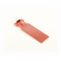
// Sensor pins
#define sensorPower 7
#define sensorPin A0

// Value for storing water level
int val = 0;

void setup() {
	// Set D7 as an OUTPUT
	pinMode(sensorPower, OUTPUT);

	// Set to LOW so no power flows through the sensor
	digitalWrite(sensorPower, LOW);

	Serial.begin(9600);
}

void loop() {
	//get the reading from the function below and print it
	int level = readSensor();

	Serial.print("Water level: ");
	Serial.println(level);

	delay(1000);
}

//This is a function used to get the reading
int readSensor() {
	digitalWrite(sensorPower, HIGH);	// Turn the sensor ON
	delay(10);							// wait 10 milliseconds
	val = analogRead(sensorPin);		// Read the analog value form sensor
	digitalWrite(sensorPower, LOW);		// Turn the sensor OFF
	return val;							// send current reading
}
sensor readings as motor control
to merge, the poti value needs to be replaced with the new sensor value, and the map max value adjusted
DHT merge:
#include <DHT.h>;
#include <ESP32Servo.h> //this

Servo twister; //this
//Constants
#define DHTPIN 21     // what pin we're connected to
#define DHTTYPE DHT22   // DHT 22  (AM2302)
DHT dht(DHTPIN, DHTTYPE); //// Initialize DHT sensor for normal 16mhz Arduino


//Variables
int chk;
float hum;  //Stores humidity value
float temp; //Stores temperature value

void setup()
{
    Serial.begin(9600);
    dht.begin();
    twister.attach(25); //this

}

void loop()
{
    //Read data and store it to variables hum and temp
    hum = dht.readHumidity();
    temp= dht.readTemperature();
    //Print temp and humidity values to serial monitor
    Serial.print("Humidity: ");
    Serial.print(hum);
    Serial.print(" %, Temp: ");
    Serial.print(temp);
    Serial.println(" Celsius");
    delay(2000); //Delay 2 sec.

    int degree = map(temp, 0, 36, 0, 180); //this, update temp with your value
    twister.write(degree);

}
23-04-24 l͓̽i͓̽n͓̽k͓̽i͓̽n͓̽g͓̽ t͓̽h͓̽e͓̽ r͓̽e͓̽a͓̽l͓̽m͓̽s͓̽
Using the ESP32 to create a hotspot and serve a simple webpage on http://192.168.4.1/ when connected.
/*
  WiFiAccessPoint.ino creates a WiFi access point and provides a web server on it.

  Steps:
  1. Connect to the access point "yourAp"
  2. Point your web browser to http://192.168.4.1/H to turn the LED on or http://192.168.4.1/L to turn it off
     OR
     Run raw TCP "GET /H" and "GET /L" on PuTTY terminal with 192.168.4.1 as IP address and 80 as port

  Created for arduino-esp32 on 04 July, 2018
  by Elochukwu Ifediora (fedy0)
*/
#include <WiFi.h>
#include <WiFiClient.h>
#include <WiFiAP.h>

#define LED_BUILTIN 23   // Set the GPIO pin where you connected your test LED or comment this line out if your dev board has a built-in LED

// Set these to your desired credentials.
const char *ssid = "joseph";
const char *password = "knierzinger";

WiFiServer server(80);


void setup() {
  pinMode(LED_BUILTIN, OUTPUT);

  Serial.begin(115200);
  Serial.println();
  Serial.println("Configuring access point...");

  // You can remove the password parameter if you want the AP to be open.
  // a valid password must have more than 7 characters
  if (!WiFi.softAP(ssid, password)) {
    log_e("Soft AP creation failed.");
    while(1);
  }
  IPAddress myIP = WiFi.softAPIP();
  Serial.print("AP IP address: ");
  Serial.println(myIP);
  server.begin();

  Serial.println("Server started");
}

void loop() {
  WiFiClient client = server.available();   // listen for incoming clients
  int sensorValue = analogRead(34);
  if (client) {                             // if you get a client,
    Serial.println("New Client.");           // print a message out the serial port
    String currentLine = "";                // make a String to hold incoming data from the client
    while (client.connected()) {            // loop while the client's connected
      if (client.available()) {             // if there's bytes to read from the client,
        char c = client.read();             // read a byte, then
        Serial.write(c);                    // print it out the serial monitor
        if (c == '\n') {                    // if the byte is a newline character

          // if the current line is blank, you got two newline characters in a row.
          // that's the end of the client HTTP request, so send a response:
          if (currentLine.length() == 0) {
            // HTTP headers always start with a response code (e.g. HTTP/1.1 200 OK)
            // and a content-type so the client knows what's coming, then a blank line:
            client.println("HTTP/1.1 200 OK");
            client.println("Content-type:text/html");
            client.println();

            // the content of the HTTP response follows the header:
            client.print("<meta http-equiv='refresh' content='0.1'>");
            client.print("<style>body{background-color:red;}</style><br>");
            int objectValue = map(sensorValue, 0, 4096, 0, 200);
            client.print("<style>.object{background-color:black;}</style><br>");
            client.print("<style>.object{width: 400px;height:400px;}</style><br>");
            client.print("<style>.object{border-radius:"+String(objectValue)+"px; }</style><br>");

            client.print("<h1>eviltwin data " + String(sensorValue) + "</h1><br>");
            client.print("<div class='object'></div><br>");
            client.print("Click <a href=\"/H\">here</a> to turn ON the LED.<br>");
            client.print("Click <a href=\"/L\">here</a> to turn OFF the LED.<br>");

            // The HTTP response ends with another blank line:
            client.println();
            // break out of the while loop:
            break;
          } else {    // if you got a newline, then clear currentLine:
            currentLine = "";
          }
        } else if (c != '\r') {  // if you got anything else but a carriage return character,
          currentLine += c;      // add it to the end of the currentLine
        }

        // Check to see if the client request was "GET /H" or "GET /L":
        if (currentLine.endsWith("GET /H")) {
          digitalWrite(LED_BUILTIN, HIGH);               // GET /H turns the LED on
        }
        if (currentLine.endsWith("GET /L")) {
          digitalWrite(LED_BUILTIN, LOW);                // GET /L turns the LED off
        }
      }
    }
    // close the connection:
    client.stop();
    Serial.println("Client Disconnected.");
  }
}

