Wang SI24

Loitering is about trust
When human going out of their shelter, they hunting the external information for their brain.
If loitering is a bridge connecting us (animals) to our surroundings (space), do we trust this bridge?
As an animal, Do you Trust the Space for loitering?
As a space, Do you Trust the Animal doing the loitering?
As a Space for Animal
int Space = City;
Do you trust the Space for loitering?
How does the space accommodate animals to loitering?
The Mosquito
The Mosquito or Mosquito alarm is a machine used to deter loitering by emitting sound at high frequency. In some versions, it is intentionally tuned to be heard primarily by younger people. Nicknamed "Mosquito" for the buzzing sound it plays, the device is marketed as a safety and security tool for preventing youths from congregating in specific areas.
Data Collection and Analysis for Public Spaces
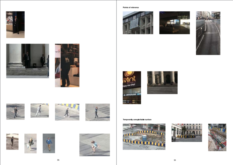
The "Footfall Almanac" examines the redesign of the Muntplein in Brussels, highlighting its transformation into a versatile, readable public space. The square, central to civic and commercial activities, underwent a redesign in 2012 to enhance its usability and integration with surrounding areas. Surveillance mechanisms, such as CCTV and wireless tracking, monitor pedestrian movements, raising privacy concerns. These systems, used for security and retail analytics, reveal tensions between public space optimization and individual privacy.
https://constantvzw.org/site/IMG/pdf/footfall-almanac-2019-lores.pdf
Checking point
In games, Checkpoints are saving the player’s state, so they could resume the point if they fail.
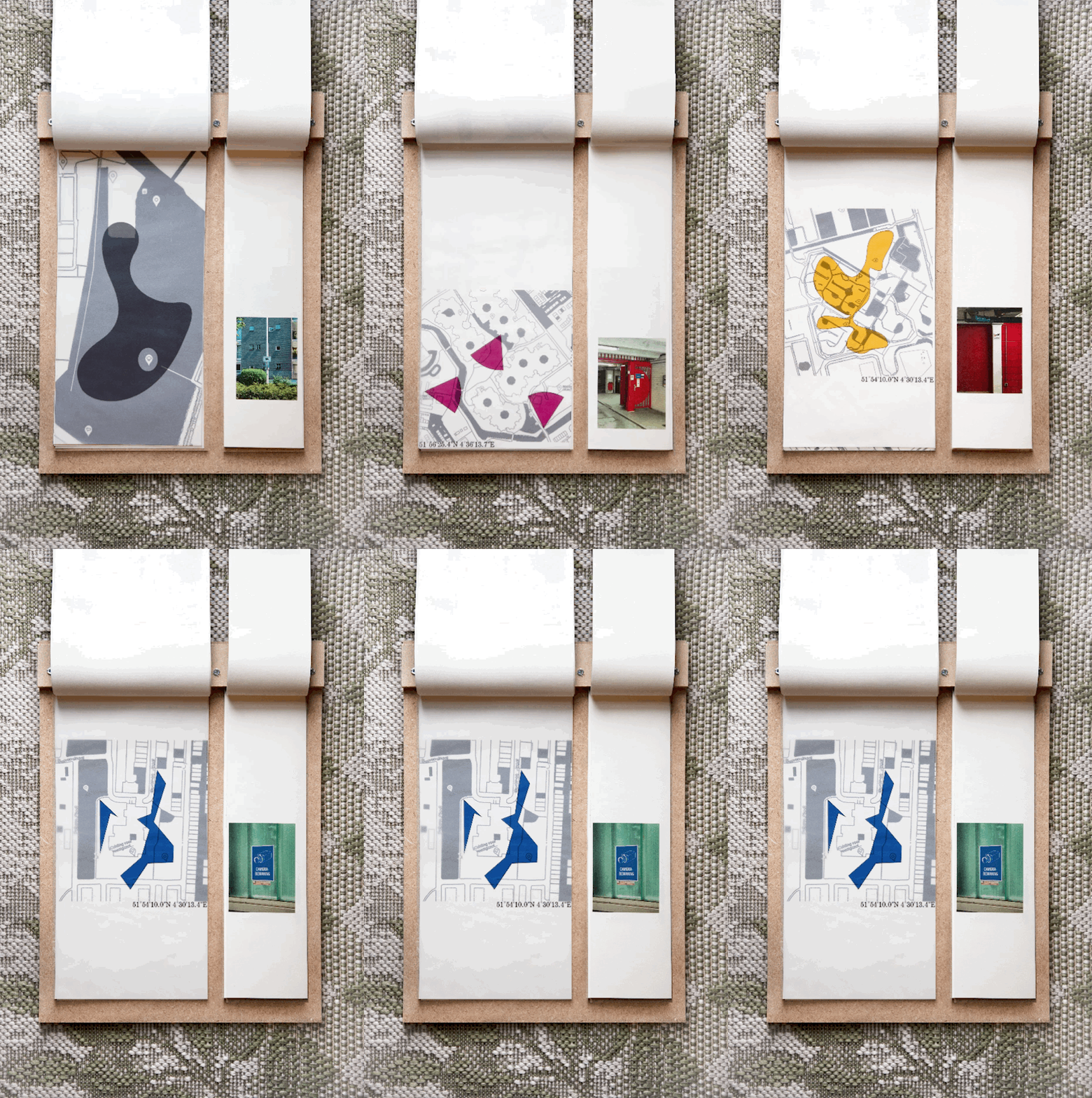
Checkpoint is a Labyrinth about the camera zones in the city, related to the checking points in the games, using the camera zone as a checking point to connect the path, also explore the relationship between the player and the people behind the monitor.
In the Labyrinth, the path that the player takes will leave no traces, but the camera zones will leave traces as checkpoints that save the player's status. By accepting cookies, you will pass through or drop into various camera zones, though you will never see the saved images captured by the government.
Camera Zone
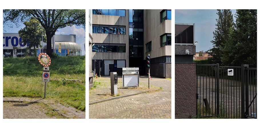
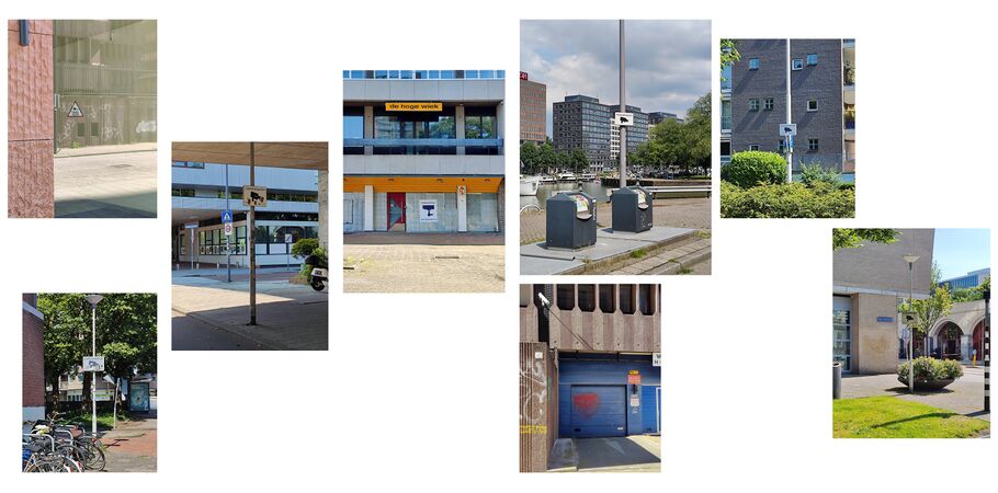
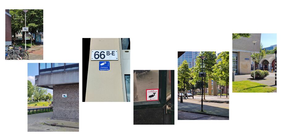
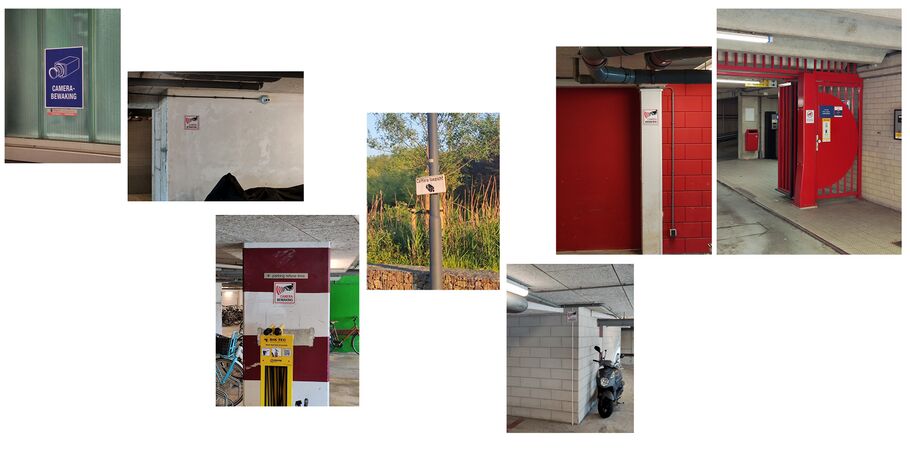
While loitering in the city, I found about 20 cameras in different places. Most of them are close to parking areas for cars and bikes and have a similar "camera brewing" sign.
Path setting
Rather than a linear map like Monopoly, the checkpoint is filled with more random open positions, creating a blank path.


Connection
Like a monitor screen, each checkpoint is a momentary record, with blank spaces between each record area. We could connect each area into a random structure.


Area/Zone/Region/Capture


Puzzle
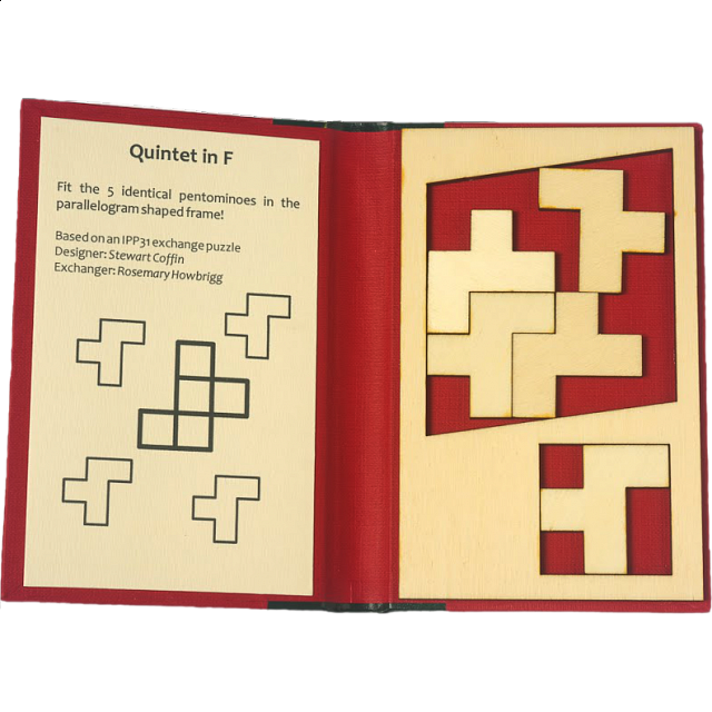


https://www.stanza.co.uk/timescraper/index.html
Process
Inspired by a children’s labyrinth toy, I wanted to blend a playful, absurd game with a commentary on monitored spaces. Rather than giving the project a serious tone, I wanted it to feel like a strange game, one that invites interaction without imposing a “message.”
In my research, I noticed how people have conflicting feelings about CCTV and monitored zones. Some feel safer with surveillance at night, while others feel it invades their privacy. To explore this myself, I rode my bike through various monitored zones, experiencing them as if I were the metal ball in a labyrinth game.(Although I couldn’t find a metal ball for my labyrinth, I used an eraser and kept rolling it until it gradually shaped into a ball.)
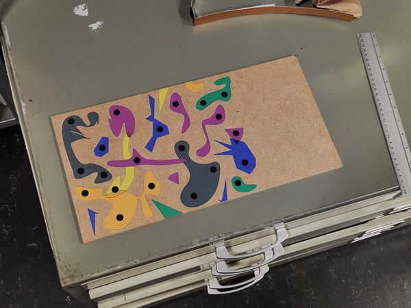
I mapped out these zones, drawing them in different shapes and colors. Using a UV printer, I printed these patterns onto a wood board, recreating the surveillance layout as a playful labyrinth. For the cover, I created a zine that serves as a sort of game manual. Inside, the zine is split into two sections: on the left are maps and patterns of the monitor zones, and on the right are photos I took of those same areas. The order is intentionally mixed, inviting players to create their own pairings as they navigate the game.
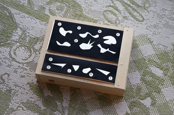
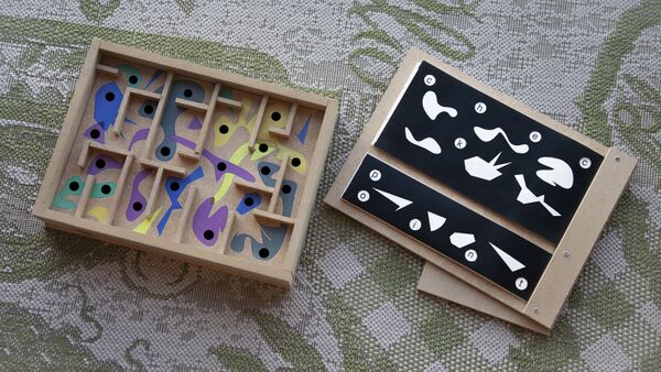
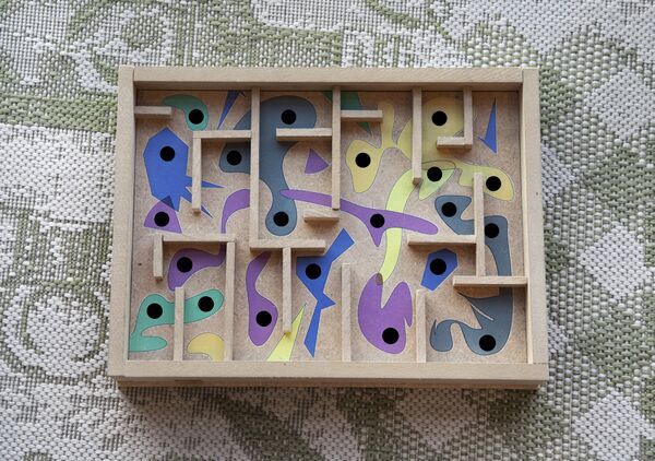
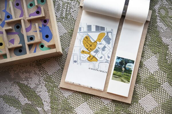
Ge Yulu - Eye Contract

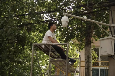
Ge Yulu’s 2016 project Eye Contact, Ge positioned himself in front of a surveillance camera and stared directly into the lens for hours, then negotiated with a security guard to buy the footage. “It represented the elimination of the barriers separating us,” Ge told Ding Yining and Shi Yangkun for Sixth Tone. “When the guy copied the clip for me, he was no longer part of the system.” He said, "I searched for surveillance cameras nearby, set up a tripod, climbed to a close distance with the surveillance camera, and then faced it directly. Normally, surveillance is to watch over us, but can't I also watch it? Here, what I question is a kind of surveillance power. I can't make any substantive changes to it; I just stare at it. I strive to stare for a few hours to make the person watching me from behind aware or to have a moment of eye contact between us. I feel that would be great. I think it's a romantic thing because every day, someone watches these streets behind the camera. Suddenly, when two pairs of eyes meet, I feel there will be a moment of warmth."
As an Animal for Space
int Animal = Human;
Protocols for loitering
At the beginning, we make the protocol for loitering, exchange the protocol and recording the things we found during the loitering.
As an unstable factor, interfering factor
Do you trust the Animal that loitering?
In this section, we consider humans as an unstable factor that can infect the Space. They are set to break the order as unstable elements and are being evicted.
- Using the protocol, I keep walking in the center, looking for a group of people. Until I find a group of tourists, I pretend to be one of them, walking with them in a straight line and taking pictures of the square house.
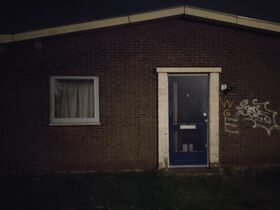
- Wearing a metal tab under the shoes, snipe-walk through the quiet community without making any noise even meet someone drinking beer in the yard, pretend to be an extra actor from The Walking Dead.
- Using a specific frequency, to connect with people walking forward to different direction.
- Randomly ring the bell at any door, record the sound, and run as fast as you can.
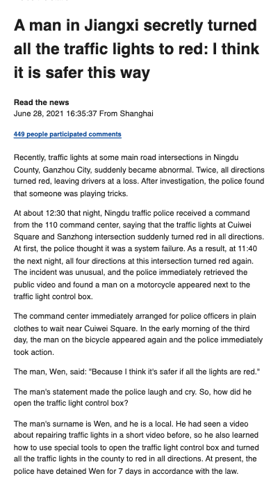
As a traffic controller, make the world safer.
A Walk with the Red Line / Ein Spaziergang mit der Roten Linie
(Details might be wrong, I didn't find more archives about this performance.)
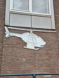
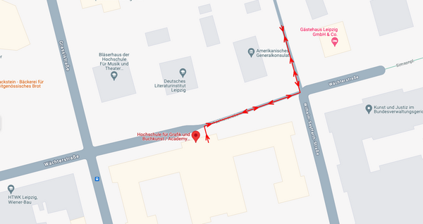
During the Rundgang 2024 at HGB Leipzig, I saw a performance by a Chinese performance artist Haiguang Li. He loitered around the American Embassy from 3 pm to 7 pm, which is directly across from HGB. Visitors watched this performance through a small window on the 3rd floor of HGB. The connection between the visitors and the performer was gazing through this window.
As he loitered, the guards at the American Embassy began to notice him and started walking alongside him across the fence.
In this performance, the unstable loitering connected the guards and the visitors gazing through the window, creating a subtle connection.
As a different Animal
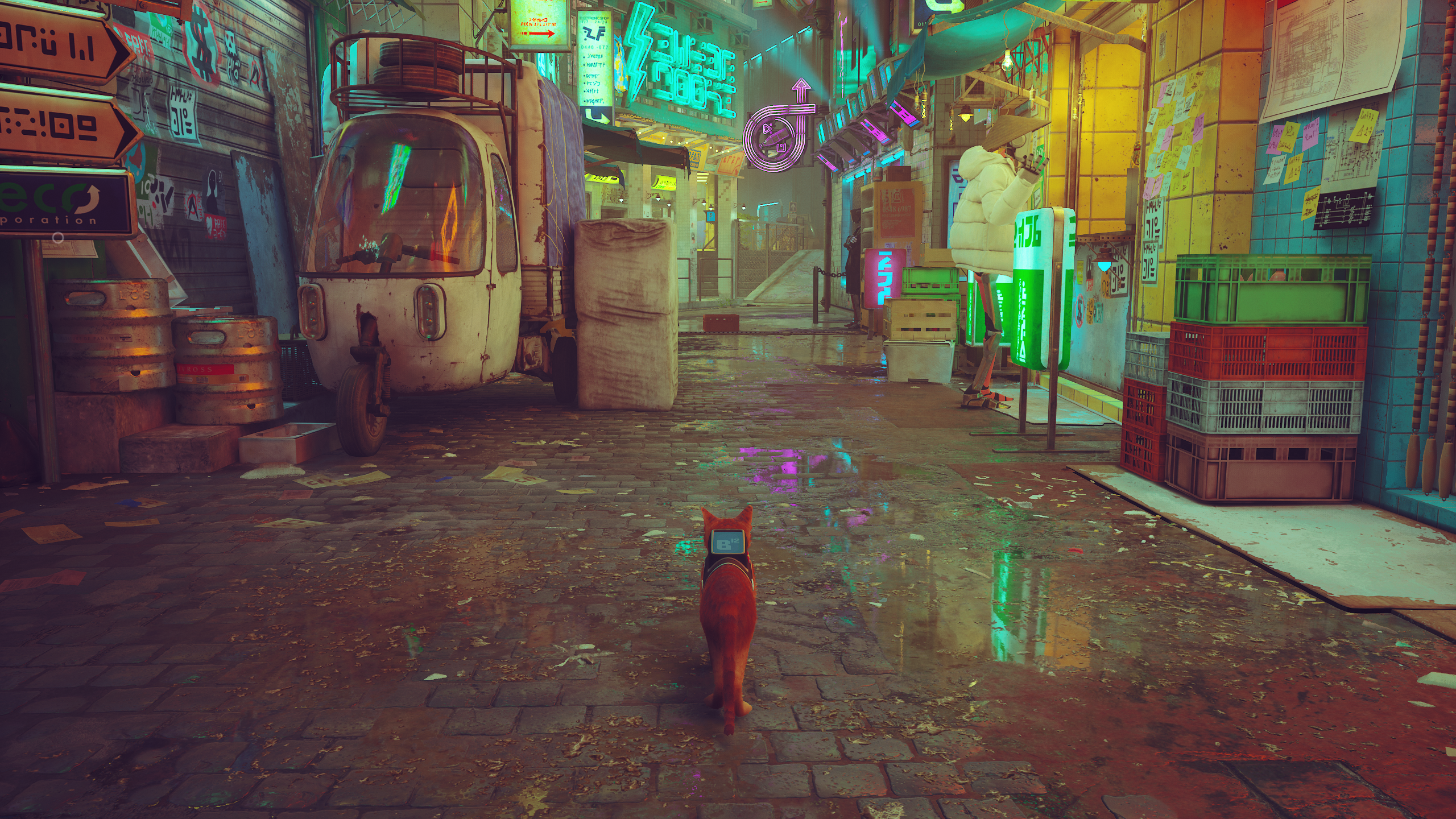
Loitering as another species, providing a different perspective and experience. Like the game "Stray", players could navigate the world as a cat. This loitering concept could expanded to various species, a high mobility bird or a fish surfing in the river.
As a TV remoter
Midi Controller
Research
Main Idea
Rain Receiver is actually a midi controller but just by using sensor.
Most logic of a MIDI controller is to help users map their own values/parameters in the DAW, using potentiometers, sliders, buttons for sequencer steps (momentary), or buttons for notes (latching). The layout of the controls on these devices usually features a tight square grid with knobs, which is a common design for controllers intended for efficient control over parameters such as volume, pan, filters, and effects.
I would like to make some upgrades in the following two ways:
the layout
During an period of using pedals and MIDI controllers for performance, I've organized most of my mappings into groups, with each group containing 3 or 4 parameters.
For example,
the Echo group includes Dry/Wet, Time, and Pitch parameters, the ARP group includes Frequency, Pitch, Fine, Send C, and Send D.
In such cases, a controller with a 3x8 grid of knobs is not suitable for mapping effects with 5 parameters, like the ARP. A structure resembling a tree or radial structure would be more suitable for the ARP's complex configuration.
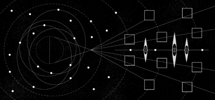
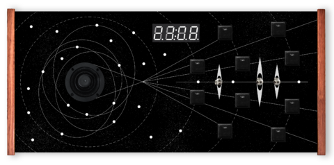
The structures, such as planets and satellites, demonstrate how a large star can be radially mapped to an entire galaxy; A tiny satellite orbiting a planet may follow an elliptical path rather than a circular one; Comets exhibit irregular movement patterns. The logic behind all these phenomena is similar to the logic I use when producing music.
the function
With more creative Max for Live plugins and VST plugins being developed, some require more than just potentiometers, sliders, and buttons for optimal use. For example, controlling surrounding sounds needs a 360-degree controller, which does not map well with a potentiometer that operates on 0-127 values. However, a joystick, which maps to both X and Y axes simultaneously, could provide a better experience.
I would like to add a joystick, touchpad, LDR, or sensors to improve the user’s experience.
further steps
Puzzle blocks game
when I'm drawing the drafts, I still thinking about block game, use the wood stick/block to make a real puzzle game, so the logic is let the sliders influence each other in a physical way. The sliders will became to a path, some slider will also not able to use when the other sliders are occupied the place.
To build a puzzle blocks midi controller, I still need:
- [ ] Buy sliders for about 9 or more.
- [ ] Cutting Wood blocks in wood station.
- [ ] Design the puzzle path.
Issues
In the process of changing the way of controlling sound, the core logic is to build a connection(mappings) of various items. Same as the Html sound experiment.
Chips like the UNO are tricky because they can't use 'midiusb.h'. The MIDI signal is hard to recognize even with Hairless MIDI. I could use the Standard Firmata with the Max plugin, but the value of the potentiometer is not stable. I attempted to add a 'potThreshold' but don’t know how to modify the Standard Firmata.
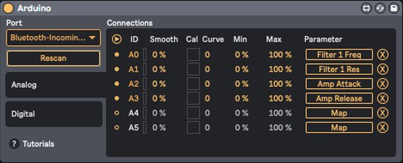
In this case, I have to switch to Leonardo or Micro.
Reference
https://dartmobo.com/dart-kombat/


 https://www.matrixsynth.com/2017/01/polytik-new-project-via-artists.html
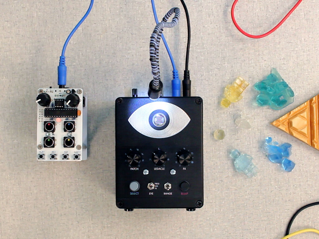
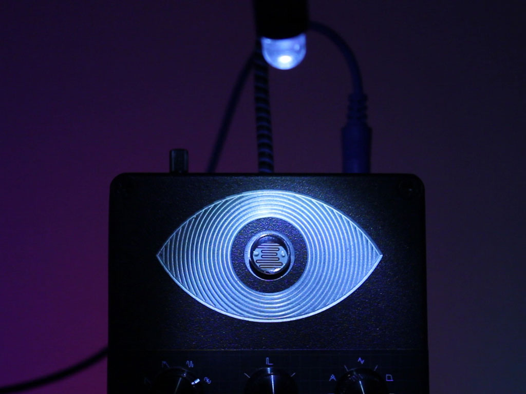

https://bleeplabs.com/product/thingamagoop-3000/
https://www.bilibili.com/video/BV1Bj411u72k/?spm_id_from=333.788.recommend_more_video.0
https://www.bilibili.com/video/BV1wx4y1k7pc/?spm_id_from=333.788.recommend_more_video.-1
https://www.youtube.com/watch?v=a8h3b26hgN4
https://ciat-lonbarde.net/ciat-lonbarde/plumbutter/index.html
Insperations
Stars


Chains/With saw gear


Layer
This could use a Dual potentiometer from the Guitar.


PCB etching
For patterns, and touch function

Format
A moving midi controller, using the same parameter to control the move, but then I’ll need a controller to control the midi controller.
A clock with various LDR, activated by the second clock pointer. This could become a clock sequencer.
A sandbox with buildings or cars or trees, the model will be the knob of the potentiometer.
A controller to hold, with several buttons on it.
Exterior
the box probably needs to use plastic but not iron(too heavy), or wood(not stable, even through wood still needs the laser cut) maybe the acrylic board.
Components
6-8 knobs for potentiometer;
4 or 8 buttons;
a slider or two?
Maybe a LDR?(but how to map the LDR to midi signal??- maybe a button to active the LDR, and a light to show of the LDR is turn on or off, and when using the LDR is the same logic to map in the live. But is the LDR need a cover?)
A arcade joystick potentiometer for controller the 360 degree values like the surrounding sounds.
ADXL345 - 3 axis(for the Hands)
Boards/Chips
Arduino Leonardo / Pro micro. Multiplexer
Basic Code Test
with the modify X3 version the buttons and potentiometers are finished but still don’t know how to add the slider and the joystick.(for the Ableton live mapping part actually is not a problem, just need to map to the X and Y, the circle is just a appearance. So it is important to get the X and Y parameter from Arduino and transfer to the midi format.)
  #include <MIDI.h>
  #include <ResponsiveAnalogRead.h>
  const int N_POTS=3;
  int potPin[N_POTS] = { A1, A2, A3};
  int potCC[N_POTS] = {11, 12};
  int potReading[N_POTS] = {0};
  int potState[N_POTS] = { 0 };
  int potPState[N_POTS] = { 0 };
  int midiState[N_POTS] = { 0 };
  int midiPState[N_POTS] = { 0 };
  const byte potThreshold = 6;
  const int POT_TIMEOUT = 300;
  unsigned long pPotTime [N_POTS] = {0};
  unsigned long potTimer [N_POTS] = {0};
  float snapMultiplier = 0.01;
  ResponsiveAnalogRead responsivePot[N_POTS] = {};
 void setup(){
 Serial.begin(9600);
 MIDI.begin(MIDI_CHANNEL_OMNI);
 for (int i = 0; i < N_POTS; i++){
   responsivePot[i] = ResponsiveAnalogRead(0, true, snapMultiplier);
   responsivePot[i].setAnalogResolution(1023);
   }
 }
 void loop(){
 for (int i = 0; i < N_POTS; i++){
   potReading[i] = analogRead(potPin[i]);
   responsivePot[i].update(potReading[i]);
   potState[i] = responsivePot[i].getValue();
   midiState[i] = map(potState[i], 0, 1023, 0, 128);
   int potVar = abs(potState[i] - potPState[i]);
   if (potVar > potThreshold){
     pPotTime[i] = millis();
   }
   potTimer[i] = millis() - pPotTime[i];
 if(potTimer[i] < POT_TIMEOUT) {
     if (midiState[i] !=midiPState[i]){
       Serial.print("Pot ");
       Serial.print(i);
       Serial.print(" | ");
       Serial.print("PotState: ");
       Serial.print(potState[i]);
       Serial.print(" - midiState: ");
       Serial.println(midiState[i]);
       MIDI.sendControlChange(potCC[i], midiState[i], 1);
       midiPState[i] = midiState[i];
     }
       potPState[i] = potState[i];
    }
   }
  }
shopping list
leonardo
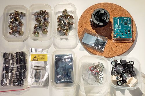
expander cd4067
potentiometer 6
buttons
mpr121
joystick
slider
ledbutton
Process
Step 1: Design the hardware logic/function
- Joystick: Controls X and Y axes.
- 3mm White LED: Shines with changes in X and Y values, indicating the joystick's rate.
- Buttons: Divided into two groups by pitch.
- Button LEDs: Shine when the sequencer mode is on; light up when the Hold mode is on.
- Toggle Switch 1: Pitch shift (+12/-12) for Group 1.
- Toggle Switch 2: Pitch shift (+12/-12) for Group 2.
- Toggle Switch 3: Left position: Sequencer mode; Middle position: Mono mode; Right position: Hold mode.
- Rotary Encoder Potentiometer: Controls the tempo when the sequencer mode is active.
Step 2: Test the basic functions with components
- The joystick can control any parameters in Ableton Live, including the surrounding sounds.
- The buttons function correctly for playing notes or activating items on/off.
- The toggle switches can shift pitch and control function modes.
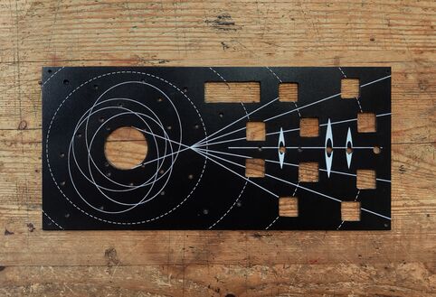
Step 3: Design the front panel
Design the front panel with references to the solar system and universe exploration drafts. Connect the two parts based on a visual system.
Draft about the drill positions
Step4: Aluminium board drill
- 4.1: Cut a 15cm x 32cm piece from the aluminium board.
- 4.2: Print the marks for drilling.
- 4.3: Attempt CNC milling - Failed-not possible to use on metal material, only wood.
- 4.4: Attempt laser cutting - Failed-aluminium board is too thick.
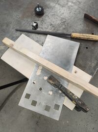
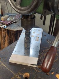
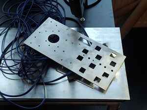
- 4.5: Start using hand tools: first, drill the circles in the square, then use a metal file to grind off the edges. Use different sizes of drills to drill all the circles on the board.
- 4.6: Grind and test the size of each component.
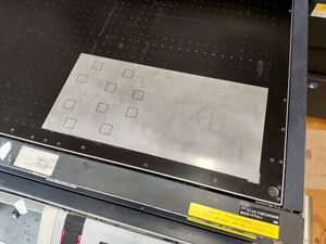
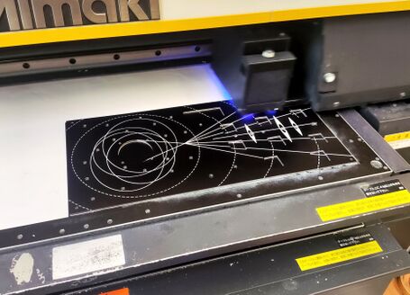
Step5: Print the final pattern on it use the UV printer
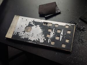
- 5.1: Using the UV printer to directly print the pattern is tricky if you have a design like this. I think it’s better to print it first and then drill according to the printed pattern, as it’s hard to align the patterns with the holes. The colors turned green and blue, and the positions were all wrong during the first attempt, so I had to remove all the print.
- 5.2: The second time, I separated the layers to print twice. I printed the black layer first, reversed the color of the white patterns and overprinted on the black layer. Although the positions were still a bit offset, the color was much better than the first time.
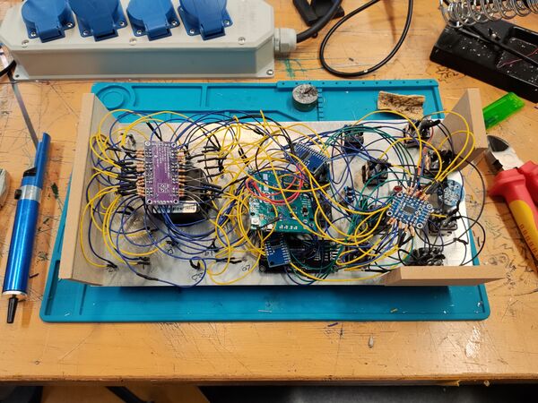
Step6: Soldering the wires.
Basic wires/connections
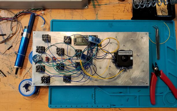
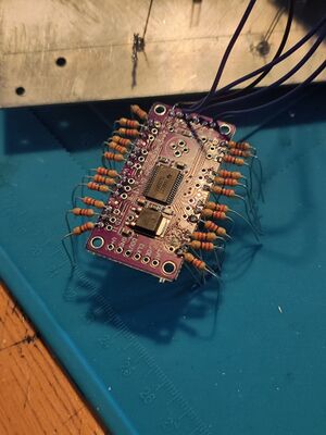
To solder better the two multiplexers on the Arduino, I removed the headers on the Arduino, but broke some digital pins on it during this process which causing the connection is unstable, and make the situation harder as I have a very limited digital pins.
I’m very regret.
Adding the Led Divers
I’ve been testing the first multiplexer with the buttons, joystick, and two toggle switches. The functions are working well. The other part with the display and encoder is also working well individually.
After I soldered these components together, the issue arose, starting my two-week cycle of happy/depressing debugging.
Issue 1
I don’t know how to handle two multiplexers at the same time, specifically how to define the second multiplexer as MUX2 or something similar. With the bad connection of the broken digital pins on the Arduino, I don’t even know if the current issue is related to the code or the connections. I tried different approaches, but I could only get signals from MUX1. When I touched the items on MUX2, I received random, incorrect messages.
Solution: Define the two multiplexers in this way:
 // Multiplexer setup
 CD74HC4067 mux1(2, 3, 4, 5);
 CD74HC4067 mux2(12, 9, 13, 11);
 const int mux1_signal_pin = A0, mux2_signal_pin = A1;
 void setup() {
 pinMode(mux1_signal_pin, INPUT_PULLUP);
 pinMode(mux2_signal_pin, INPUT_PULLUP);
 }
issue 2
I have 24 leds to map with the Joystick, but I noticed that I also have 10 leds on these buttons, and the Multiplexer cannot digital read and digital write at same time as I expected.
Solution: I bought another 12 channel Led driver...
 tlc59711.begin();
 tlc59711.write();
 tlc5947.begin();
 tlc5947.write();
And this Led driver TLC59711 caused another issue: The Led driver can only turn on one led as a group but not able to turn on each one individually. Solution:
tlc59711.setLED(0, 3000, 0, 0);
In this definition the (0, 3000, 0, 0) are actually not means the RGB color but means (port/group 0, Led 1 brightness, Led 2 brightness, Led 3 brightness);
Issue 3
After I mapped all the LEDs and combined all the codes together, I found that the encoder stopped working. Additionally, in Sequencer mode, the sequencer tempo was not matching the set tempo, and I couldn't change the tempo using the encoder.
After several days of debugging, I commented out the potentiometer part and the TLC part, but they still did not work. I'm unsure if this is due to insufficient storage/program space or inadequate power supply.
So, I reverted to the first version of the code, which only had buttons and three modes. I tried to shorten the code and add each part step by step to identify which part was causing the Sequencer mode issue. When I shortened all the codes, I found that the encoder started working and could control the sequencer tempo. However, the sequencer would automatically slow down. I'm not sure if this is good news or not.
I had to debug again and found that the sequencer started to slow down once I added tlc.write(), whether it was inside the Void.SeqMode or not, and regardless of whether it was tlc5947.write() or tlc59711.write(). So, I tried modifying Void.SeqMode by adding a timer inside it, which finally fixed the slowing down issue.
Issue 4
After fixing that big issue, I found I had missed two LEDs that were supposed to show the mode change. After adding these two LEDs, the encoder stopped working again, which drove me crazy and made me want to throw this wood box into the Maas river.
Once again, after debugging, I found that in the potentiometer part where I mapped 22 LEDs, the LEDs kept refreshing to reflect the changing potentiometer values. This conflicted with the encoder and prevented it from receiving signals.
I modified the potentiometer part to make the LEDs change only after the potentiometer state changed. This made the full code more efficient and fixed the encoder issue.
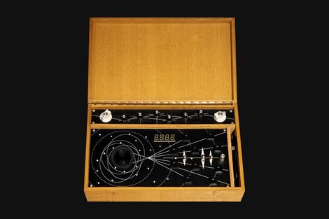
Step9: Make a shell for it.
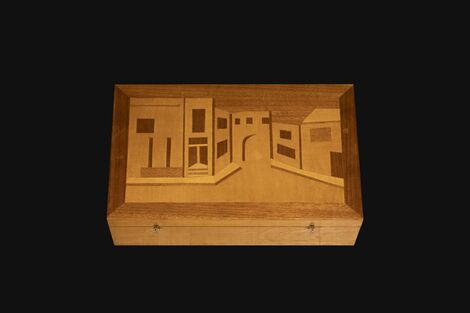
I found this wood box in a corner of a flea market. I felt it was very suitable for the controller. I cut some wood to divide the interior space. With all the code finally working, I added another section with 8 potentiometers at the top of the box to provide more control, sanded off the original yellow wood color and painted it with a darker oak finish.
Post-Process
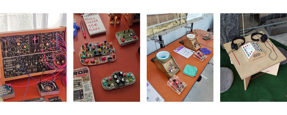
On 31.08, I went to DutchModularFest in Utrecht. I found many interesting synthesizers and even a sound workshop. It was a great opportunity for me to potentially ask these talented creators about the processing details and conduct some market research.
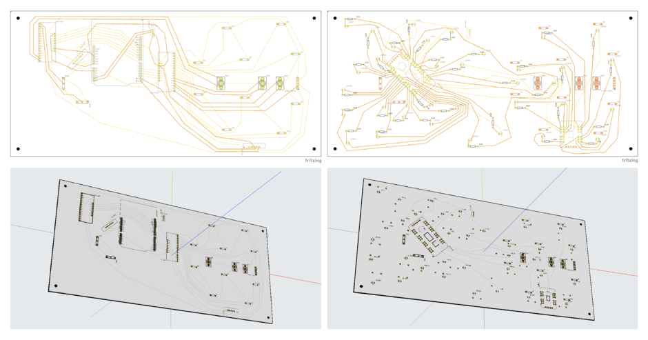
With some learning about "factory communication skills," I contacted with some factories in China and started placing the first order for the panel and PCB, aiming to make the MIDI controller more epic and stable for use.
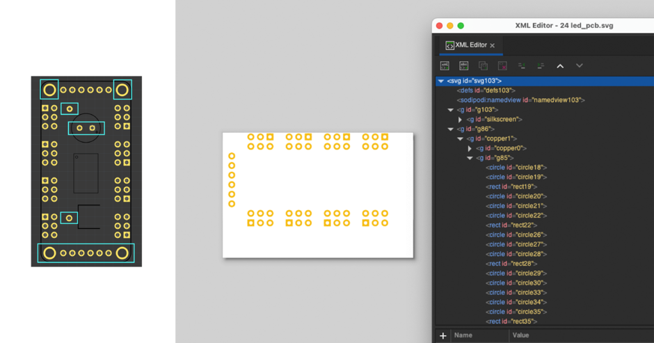
When I used the 24-channel LED driver model from Adafruit on Fritzing, I found that the four drilling holes and the outputs on the right side were unnecessary and wasted a lot of space. Since it is a very small chip with limited space for connecting 48 wires, I decided to edit it as a new part. However, no matter how I tried, Fritzing couldn't recognise it after I deleted the extra holes in Inkscape.
After a lot of experimentation, I discovered that the folder structure gets modified when you open SVG files in Inkscape. Fritzing only recognises a specific folder structure: the copper0 layer must be inside the copper1 folder, and both should be under the silkscreen layer.
 <g id=“xx”>
   <g id=“silkscreen”>
 <g id=“xx”>
   <g id=“copper1”>
     <g id=“copper0”>
Javascript Club - Gamepad/Midi API
Joining Rosa's JavaScript club has been really inspiring and helpful. I think I finally found a way to link the HTML I made last trimester with physical controls.
Gamepad to control the Helicopter
I tried to use the gamepad to control the cursor at first, the movement is easy to map but the click/mouse down/mouse up is hard to simulate, with my broken coding, I failed and came up with more stupid ideas, use the WASD key to control the helicopter then map the Index 0,1,2,3,4,5 to the WASD and J K(which also failed at the end and took more time).
Protocol:
1, Key control - using WASD to control the helicopter.
2, Replace the draggable by key control in the main codes, also add the J and K to control the fill and drink.
3, Map the Index 0,1,2,3,4,5 of the gamepad to the WASD and J K - Failed
4, Using the same approach of key control, let the values of the helicopter movements echo to the Index 0,1,2,3,4,5 == button pressed.
In the end, I got a Beer Robber version with both able to use key and gamepad control.
Midi controller to control the slider block
At first I meet some issues that the midi controller is only controlling the slider(css) moving but not able to control the sound values, I found the midi code part is outside of the pitch loop, which caused the effect not able to defined.
After the issue fixed, I also mapped the buttons to control the pitch blocks in the html.
Browser extensions/PMoMM
The Browser Sound plugin is a browser-based tool that adds various effects to your audio and video.
This browser-based plugin could easily accessing samples for your projects.
Unlike plugins in digital audio workstations (DAWs), this plugin operates directly in your web browser. It will distort your audio or video when you play them in the browser.
Regarding my recent experiments, I've been using pizzicato.js for sound experiments, but I've found the selection of sound sources to be limited.
To address this limitation, I'm interested in creating a browser-based plugin that allows users turn the Browser into an instrument, a sampler, by searching and using their own samples from various websites and platforms.
What is it?
The Browser Sound plugin is a browser-based tool that adds various effects to your audio and video, which could easily accessing samples for your projects.
Why make it?
1,The plugin addresses the limitation of traditional DAW by providing users with a convenient way to access and manipulate audio samples directly within their web browser. 2,It could expand the possibilities of sound experimentation, allows users turn the Browser into an instrument, a sampler, by searching and using their own samples from various websites and platforms.
Workflow
1, Research on the browser plugins. 2, Sound design part, list the effect could be using on the sampler, design the audio effect chain. 3, Coding part on browser extension. 4, Based on the coding part to fix the sound design. 5, Interface design for the plugin. 6, Based on the Interface design to redesign the code logic. 7, Test and fix any bugs. 8, Using the plugin to record a sound file.
Timetable
Total: 22 days 12 h 0 min 0 s. 1, Research: 3 days. 2, Sound design part: 3 days. 3, Coding part: 5 days. 4, Interface design: 3 days. break: 12 h 5, Bug fixing: 5 days. 6, test and record: 3 days.
Previous practice
Regarding my recent experiments, I've been using pizzicato.js for sound experiments, the sound source is using the SineWave with different frequencies, but I've found the selection of sound sources are limited, it should be able to use any audio source from the another websites and platforms.
Relation to a wider context
The Browser Sound plugin contributes to the broader landscape of digital audio production tools by offering a new approach to sound manipulation and sampling. It bridges the gap between traditional DAWs and web-based platforms, providing users with innovative ways to create and manipulate audio content.
Part II 17/04
I'm sticking with my focus on developing the "browser plugin" and finding ways to expand its functionality. As part of the project, I'm starting with research to gather insights and ideas.
Regarding references
I've explored feedback and found inspiration from projects like Pellow, which explores creating sound from browser- based data, and MIDI controllers, which could potentially be integrated to control the plugin. Experimenting with multiple browser tabs to a mixer is an interesting way to explore.
Accessibility
I've also thought about accessibility factors for the web page. Have you considered features like Speech to Text? There are existing browser extensions like Read in the Dark, Read Aloud, and Zoom In/Out that enhance accessibility. For sound-related extensions, most focus on volume enhancement or equalization, leaving room for a plugin with effects like tremolo, phaser, distortion, or even a sampler recorder, as suggested by Senka.
Does it has potential?
I think there's still some potential for the plugin, especially given the existing landscape of browser extensions and the need for more diverse sound-related tools. Im started working on it, and I'm considering using a simple JSON file and possibly an API to facilitate its development.
Part III 24/04
In the first step, I tried adding pizzicato.js to both the popup.html and background.js files, but meeting issues with it not being defined. Despite trying with a lot different approachs, even copying all the code directly into the background.js, the problem persisted.
When I adding the url src rather than library, I found there a CDN issue from the console, which is means with the Manifest version 2.0, Chrome is not able to accept using the external javascript to modifying real-time audio from tabs, due to "security restrictions", to protect user privacy and prevent malicious extensions from capturing sensitive audio content.
In this case, I have to try to use the Audio API to make this extension.
Readers
https://www.frontiersin.org/journals/psychology/articles/10.3389/fpsyg.2017.01130/full
https://www.google.nl/books/edition/The_Society_of_the_Spectacle/uZcqEAAAQBAJ?hl=en&gbpv=0
https://isinenglish.com/1-6-contribution-to-a-situationist-definition-of-play/
