VGA Glitch hack - Mr Stock workshop
Arduino_ workshop Mr Stock
VGA_Glitch_controller with Mths
1.1 Description
In this workshop we experimented with controlling the RGB signals (three channels green, blue and red) from a VGA cable. Arduino perceives and transforms the signal as hi flickering glitches displayed on TV. The main focus was to explore unknown random behaviours of the signal velocity. A Max/MSP patch was used to communicate with Arduino through the Serial port, syncing the VGA signal to the frequencies of the played audio file. A MIDI controller was sending values to the patch for mixing the color channels and adjusting the distortions of the VGA signal.
1.2 Documentation
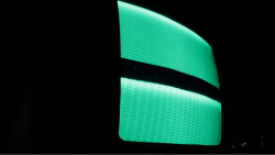
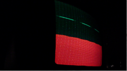
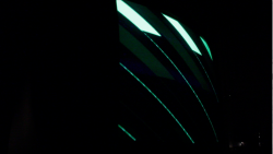
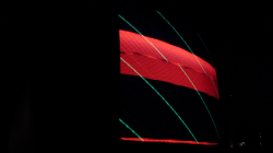 --->Full Video
1.3 How the VGA signal works?
How the VGA video signal works? There are three analog signals (0-0.7 v), used to control the color (rgb) and two digital signal - horizontal and vertical sync used for synchronisation of the video. By changing the analog levels of the three RGB signals all other colors are produced.
The electron beam must be scanned over the viewing screen in a sequence of horizontal lines to generate an image. The RGB color information in the video signal is used to control the strength of the electron beam.
The screen refresh process begins in the top left corner and draws 1 pixel at a time from left to right.
At the end of the first row, the row increments and the column address is reset to
the first column. Once the entire screen has been painted, the refresh process begins again.
1.4.a ARDUINO_part
Our starting point was project done by Sebastian Tomczak: Hacking VGA lines with arduino.
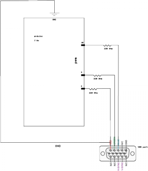
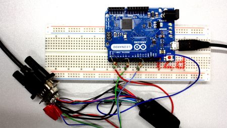
The VGA port is connected to Leonardo throughout PWM~: 3, 5 and 10 which allows us to have more control on the frequency and the signal amplitude.
more description on programming how the LUFA libary was integrated soon...
Workshop_2
2.1 Description
In this workshop I experimented with building oscilloscope out of the Tv from the Workshop_1 (VGA customer controller) The DYI oscilloscope allows observation of constantly varying signal voltages usually as a two-dimensional graph of one or more electrical potential differences. The left and the right channel are connected to the screen. One is using for the (horizontal x-axis) and the other is plotted as a function of time (vertical or y‑axis). There are two built up amplifiers connected to two eight volt external speakers. I've used Abelton to send notes to the oscilloscope. The visuals are sync to the sound input.
The video is 2' documentation on the intervention. The object could be seen as nice tool for AudioVisual performances.<video src="http://pzwart3.wdka.hro.nl/~mlakova/stockWorkshop.mp4"></video>
