RaspberryPi GPIO
Raspberry Pi GPIO pins configuration
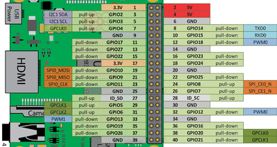
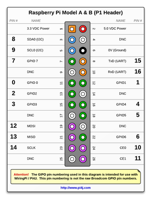
A 40-pin GPIO header is found on all current Raspberry Pi boards (unpopulated on Pi Zero and Pi Zero W). Prior to the Pi 1 Model B+ (2014), boards comprised a shorter 26-pin header
Pins
- GPIO is your standard pins that simply be used to turn devices on and off. For example, a LED.
- I2C (Inter-Integrated Circuit) pins allow you to connect and talk to hardware modules that support this protocol (I2C Protocol). This protocol will typically take up two pins.
- SPI (Serial Peripheral Interface Bus) pins can be used to connect and talk to SPI devices. Pretty much the same as I2C but makes use of a different protocol.
- UART (Universal asynchronous receiver/transmitter) is the serial pins used to communicate with other devices.
- DNC stands for do not connect, this is pretty self-explanatory.
- The power pins pull power directly from the Raspberry Pi.
- GND are the pins you use to ground your devices. It doesn’t matter which pin you use as they are all connected to the same line.
40-pin GPIO
26 pin (Pi 1)
Install
To program the GPIO pins we needed to install the Python3 Rpi.GPIO library
sudo apt-get update
sudo apt-get install python3-rpi.gpio
or
pip3 install RPi.gpio
Test: Writing to PIN
In this small script we will write HIGH & LOW values to Pin 12.
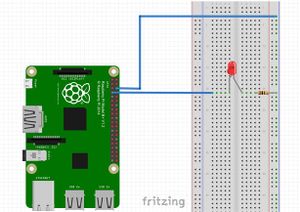
And use a LED and a 220Ω resistor to see if GPIO is operating and expecting.
Connect according to the diagram, keeping in mind that the
- LED has polarity:
- long leg: positive
- short leg: negative
- LED needs to have (220Ω) resistor, standing between its negative leg and 0Volts, in order to protect it from excessive current.
#!/usr/bin/env python3
import RPi.GPIO as GPIO
import time

LedPin = 4
GPIO.setmode(GPIO.BOARD)       # Numbers pins by physical location
GPIO.setup(LedPin, GPIO.OUT)   # Set pin mode as output

try:
    while True:
        GPIO.output(LedPin, GPIO.HIGH)
        time.sleep(1)
        GPIO.output(LedPin, GPIO.LOW)
        time.sleep(1)
except KeyboardInterrupt: # Ctl-C will interrup
    pass
GPIO.cleanup()  # clean resources used
Links
- https://pimylifeup.com/raspberry-pi-gpio/
- Basic usage: https://sourceforge.net/p/raspberry-gpio-python/wiki/BasicUsage/
- Working with inputs (a button for example): https://sourceforge.net/p/raspberry-gpio-python/wiki/Inputs/


