Prototypology/Adapterology-1: Difference between revisions
No edit summary |
No edit summary |
||
| (2 intermediate revisions by the same user not shown) | |||
| Line 19: | Line 19: | ||
[[File:Jack-trrs.jpg | center | 300px | The A/V Jack ]] | [[File:Jack-trrs.jpg | center | 300px | The A/V Jack ]] | ||
To connect to video signal of the Pi you need to solder a composite video cable to the jack connector. | |||
[[File:Pi-adapter.jpeg.png | center | 620px | The A/V Jack ]] | |||
Latest revision as of 10:55, 9 June 2022
How to connect a analog monitor to an Raspberry Pi 4?
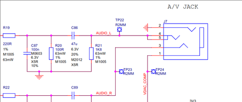
The Raspberry Pi 4 can also output an analog video signal that can be used with old CRT-Screens. Lets have a look into the official schematics [1] of the Raspberry Pi 4.
The part J7 is an A/V jack socket with four connectors:
- VDAC_COMP (the video digital to analog convertor == video signal)
- GND (the tree symbol means in the langauge of schematics Ground)
- AUDIO_R (the right audio channel)
- & 5. AUDIO_L (the left audio channel)
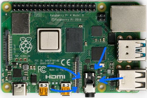
And this is how it looks on the Raspberry Pi 4:
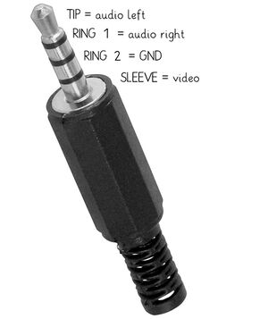
This socket is for a TRRS jack connector:
- T (TIP) is connected to AUDIO_L
- R (RING 1) is connected to AUDIO_R
- R (RING 2) is connected to GND
- S (SLEEVE) is connected to VDAC_COMP
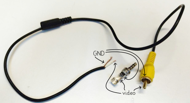
To connect to video signal of the Pi you need to solder a composite video cable to the jack connector.


