User:Eleni/Biodata Sonification
Holding myself accountable ✨
This is the beginning of a new project; I am creating my own Biodata Sonification Device using this tutorial, while also documenting my process on here!
I know next to nothing about MIDI and Galvanic Conductance, but we are experimenting (fucking around and finding out)
List of Tools
From what I've gathered from the tutorial I need:
- 3.5mm jack
- Blue (?) Capacitor 4700pf
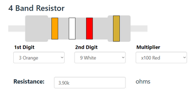
- Resistor (3.9K)
- 555 Timer IC (8pin)
- 5 LEDs (red, orange, green, blue, white)
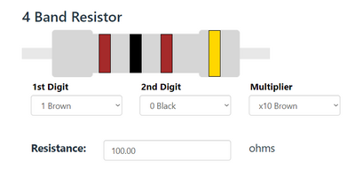
- 10 Ohm Resistor
- 11 Jumper Wires
- Solderless Breadboard
- CR2032 Button Battery 3 volts
- Adafruit Feather ESP32
- microUSB Cable
Some extra info for components
Resistor
(In Greek: Αντιστάτης) The resistor is a passive electrical component that creates resistance in the flow of electric current. In almost all electrical networks and electronic circuits they can be found. The resistance is measured in ohms (Ω). An ohm is the resistance that occurs when a current of one ampere (A) passes through a resistor with a one volt (V) drop across its terminals. The current is proportional to the voltage across the terminal ends. This ratio is represented by Ohm’s law:
R = V / I
The resistance value and tolerance are indicated with several colored bands around the component body. This marking technique of electronic components was already developed in the 1920s. Printing technology was still not far developed, what made printed numerical codes too difficult on small components. Nowadays, the color code is still used for most axial resistors up to one watt. In the figure above, an example is shown with four color bands. In this example the two first bands determine the significant digits of the resistance value, the third band is the multiplying factor and the fourth band gives the tolerance. Each color represents a different number and can be looked up in a resistor color code chart or using a resistor color code calculator. [1]


