Glare
Glare module
A gesture controllable sound interface
GLARE is a speculative interface trying to explore what lies behind the boundaries of the usual input devices. The idea for it arose out of the impression that most of music production interfaces require a deep understanding of the subject and thus impose a considerable hurdle on the average user.
Music is in itself something very intuitive and emotional and the making of it should be accessible to a broad audience, as it is something profoundly satisfying and an excellent method of (emotional self reflection) self-realization. This approach is not only aiming at providing a new controller for musicians, but to put the creation of music into the lives of individuals as a practice of leisure.
Dancing as a direct and very personal translation of music, usually on the very end of the music production process is the exact opposite. Making music could be as simple as dance.
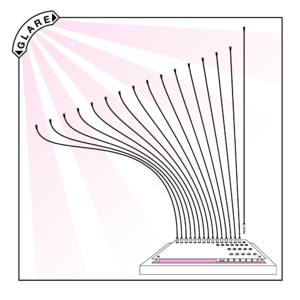
GLARE module is being controlled by gestures only and thereby works in a very intuitive way. The movements controlling the auditive content resemble the motion of dancing.
REQUIRED PARTS
PARTS FOR ASSEMBLY:
- 1 x GLARE circuit board
- 1 x Teensy 3.1 OR Teensy LC board
- 4 x ADS1115 16 Bit I2C ADC
- 16 x Light dependent resistors
- 33 x Mono audio Jack 3,5mm model PJ301M-12
- 16 x Mono audio Jack Plug 3,5mm
- 1 x Tactile Push Button 6x6mm 15mm version if available
- 1 x Toggle switch ON-OFF 2 pin
- 16 x 480 mm 2 poled cable
- 16 x 500 mm shrinking tube ø6, 4mm
- 16 x 500 mm x 2,5 mm insulated metal wire
- 18 x 10KΩ Resistor
- 2 x 1KΩ Resistor
- 73 x Female Headers (optional)
- 73 x Male Headers (optional)
- Insulating Tape
- Solder
TOOLS:
- Soldering iron
- Static light source
PARTS FOR OPERATION
- 1 x Mono audio cable 3,5mm (to connect audio output)
- 16 x Mono audio cable 3,5mm (optional; to connect devices to the control voltage output matrix)
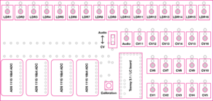
For the sake of brevity from now on the ADS1115 will be called ADC, the Teensy LC board will be called Teensy, the GLARE circuit board will be called PCB and control voltage will be called CV.
Make sure you have all the parts listed in the Parts section before you begin assembling the GLARE module! The screen-printed side of the PCB must face upwards. If you want to be able to detach the main parts you should solder male and female headers to the PCB and parts. You can also chose to solder the parts directly onto the PCB.
ASSEMBLY MANUAL:
   1. Carefully detach the GLARE PCB from the main PCB
   2. Solder 33 male headers to the 3 lines of holes on the Teensy 3.1/LC
   3. Solder 10 male headers to the line of holes on each ADC
   4. Solder the legs of the 18 10KΩ resistors to the PCB at the labeled positions
   5. Solder the legs of the 2 1KΩ resistors to the PCB at the labeled positions
   6. Solder the legs of the Tactile Push Button to the PCB at the labled position
   7. Solder 33 female headers to the 3 lines of holes surrounding the Teensy 3.1/LC label on the PCB
   8. Solder 10 female headers to each of the 4 lines of holes on the right side of the ADC 1, 2, 3 & 4 labels on the PCB
   9. Solder the legs of the Toggle switch to the PCB at the labeled position
   10. Solder the legs of the 33 Mono audio Jacks to the PCB at the labeled positions
OPERATIONAL MANUAL:
Basic operation (audio):
- Make sure the device is disconnected from power
- Plug the 16 Sensors into the upper row of 3,5mm audio jacks
- Arrange the heads of the sensors according to your preference
- Glare works best if the sensors are aimed at a single light source. You can of course experiment with different light setups
- Power the device on (the device on the sensors will automatically calibrate to the light they are exposed to so make sure they are not obscured)
- Make sure the toggle switch is in the audio playback position
- Connect the Audio output plug to an audio playback device
- After a few seconds the device will start outputting audio whenever you cast a shadow on one or more of the sensors. The volume of the audio signal will increase equivalently to the density of the shadow
- To recalibrate the LDRs hold down the pushbutton for 2 seconds
Advanced operation (CV):
- Follow steps 1 - 5 of the basic operation manual
- Make sure the toggle switch is in the CV output position
- Connect all devices you want to control to the CV outputs 1-16
- After a few seconds the device will start outputting CV for each sensor on the according CV output whenever you cast a shadow on one or more of the sensors
- To recalibrate the LDRs hold down the pushbutton for 2 seconds


