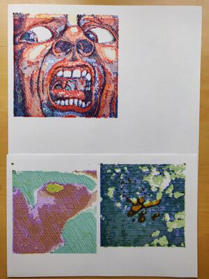
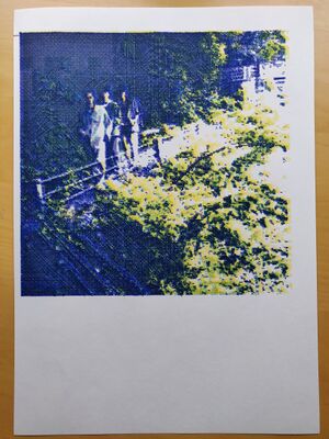
User:Thijshijsijsjss/Pen Plotting Panache/Plothatching Workflow
A documentation of my workflow for making multicolor crosshatching plots. It should (ultimately) be comprehensive for anyone by links and step-by-step guides, but is for now primarily written for my own future reference. This means that there will be many options for each of these steps, and I will limit myself to those strategies I have found to work for me.
I will make reference to several pieces of software. Notably:
- Krita, open source painting software
- Inkscape, open source vector manipulation software
- Some code I have written for crosshatching. Find it here on GitHub. Also, find it's dedicated wiki page here
Image selection
There's no real limit to what images can be plotted! These techniques are pretty flexible and powerful. However, still image selection seems to be one of the harder steps in this process.
Some things to keep in mind:
- Plotting takes quite a bit of time and attention. Not only the act of plotting itself, but also the preparations require a significant amount of time. Choose your current project accordingly.
- Monochrome plots are way faster than multicolor plots, both due to reduced plotting and prepping time. Additionally, the babysitting that tends to be automatic when penplotting is largely only important when switching out pens. One pen (one color) can be safely let free to plot without being babysat.
- Your selection of pens matters. Just like every plotter has its quirks, every combination of pens has its unique vibe. It's not a bad idea to take your options of pens into consideration for your choice of image.
- The crosshatching technique tends to work best for certain images:
- Images with high contrast; this will improve the level of detail that will be perceived in the final plot
- Multicolor images where the different pens will need to interact 'interestingly': nice pieces of overlap balanced with areas of one color.
- Multicolor images don't want to be very dark when plotted with a dark color for 'key'; the 'key' color will just cover everything
Image preparation
Dimensions
To avoid having to scale many layers individually later on, it's easiest to determine the size of your plot at the start. As the plotter is fastest in its horizontal axis, it is advised to orient your image in a way so that the largest dimension is the horizontal one (i.e. by rotating a portrait mode image). However, when wanting to make a plot as large as possible, this is obviously not always desired. In that case, keep bounds of 1100px by 1450px in mind (the full size of the paper in pixels according to Inkscape's default conversion).
My three most used choices for image width are:
- 500px: This allows for two same width plots to be placed next to eachother on the width of the A3 plotter I have been using.
- 600px: 500px plots feel quite small. I have found 600px to be the sweet spot for compact plots that still capture quite some detail.
- 1000px: this is the about the full width of the A3 plotter I have been using.
Note that this conversion between pixels and real world measurements units is actually arbitrary. This discussion has the Inkscape default conversion in mind. Relying on this conversion saves us potentially difficult conversion problems later on, and has proven reliable between plots.
Passe Partout
Eventually, we'll need to create vector paths out of the images the crosshatching software outputs. As plotting is a lenghty step, any preparations we can do to improve the plotting time, will reduce the overall time it takes to create a plothatched image. One such improvement is the way the vector paths are traced. In Inkscape, 'Centerline (autotrace)' has the best results, by far. However, it will often (~60% of the time) crash Inkscape, in which case one has to resort to less efficient tracing methods that will typicially cause each line to be drawn from it's center (effectively adding >50% extra plotting time).
By adding a white border, a 'passe partout', around your image, Centerline (autotrace) has a better chance to succeed. In fact, borders of 100px have had a 100% success rate for me (n>150). This will NOT affect the final dimensions of your plot.
- Open your file in Krita
- Go to Image > Resize Canvas
- Add 100px to the smallest of your image's dimenstions
- Click OK
- Save image (overwrite it)
Layer separation
We will separate the different color channels and save them as individual files, so that we will be able to plothatch them individually.
- Open your file in Krita
- Change color space to CMYK
- Image > Convert Image Color Space
- Choose Model: CMYK / Alpha
- Click OK
- Separate image
- Image > Separate Image
- Click OK
- Invert all layers. For each of the layers:
- Go to a layer and press ctr+I
- Save layers 'cyan', 'yellow', 'magenta' and 'black' separately. For each of the layers:
- Toggle visibility for only one of these layers
- Save (ctr+shft+S)
- Fix opacity. For each of the new images:
- Open the image with the Windows default images app
- Three dots > Change image size
- Save image (overwrite it)
Transparancy adjustments
The previous step will typically output jpg images for which the transparancy is interpreted as black. Often this is not what we want. Magically, opening an image in Windows's default image viewer and re-saving it (overwriting it) fixes the transparancy. This is a quick process. For other operating systems, I imagine Krita and Inkscape both support functionality to handle this.
Hatching
Setting parameters
Hatching each layer
Inkscape
Prepare document
We will prepare the document we will be working with. First, set the documents size:
- Go to File > Document Properties (Ctrl+Shift+D)
- Choose Format: A3 (or any other appropriate filesize). Note that this is primarily for the width, and not so much for the height of the paper (i.e. feeding a sheet of A4 paper in landscape mode to the plotter and plotting something from A3 settings that fits within the bounds of the A4 sheet will not cause any problems).
Next, create the layers for each color channel, and one additional layer that we'll use for importation and organization purposes. In the case of a CYMK plot:
- Open de Layers and Object tab by going to Layers > Layers and Objects (Ctrl+shift+L)
- Create 4 new layers with the dedicated button, or with Strl+Shift+N
- Rename the layers res, cyan, yellow, magenta, black (this is not strictly necessary, but useful for referencing layers within this guide, and also useful for yourself later on).
Steps for each color channel image
We will now do some preparations for each color we'll be plotting with. Confusingly, there are two notions of 'layer' here: the Inkscape 'layers', which can be thought of as folders that contain all the paths that sould be drawn with one pen. Then, there are the 'layers' of the physical world: layers of the same color that will be drawn on top of each other.
The following steps need to be taken for each color we're going to plot with, i.e. for each set of output layers we have created with the crosshatching software.
- Select the res layer
- Import all crosshatched layers of one color channel to the res folder. This is easiest by selecting them all in a file explorer and dragging them ONTO THE CANVAS AREA (note that Inkscape will crash when they are dragged onto the layers menu), but this can also be done one by one through Inkscape's import menu.
- For each imported object, you'll see a sublayer in Inkscape with an image. For each of these sublayers:
- Position it at (0,0) by selecting the Select Tool, selecting the relevant sublayer, and setting x and y fields to 0.
- Still with the Select Tool, select the image in the sublayer, and go to Trace Bitmap (Shift+Alt+B, Path>Trace Bitmap, or through the quick menu if it's still open)
- MAKE SURE SMOOTH CORNERS IS TICKED OFF
- Click Apply
- Move all paths that have been created to the appropriate Inkscape layer.
- Delete all contents from the res layer.
Alignment thingies
When plotting through Inkscape, the top-left corner of your plot is determined at the time of starting the plot, and all paths in that 'batch' are positioned relative to that origin point. This means that when plotting two paths with top-left corners at (X,Y) and (X+n,Y+m) (n,m>=0), these will be plotted at (0,0) and (n,m). In other words: the relative position is maintained when plotting multiple paths at a time.
When sending new paths to the plotter, however, this origin is redetermined. So when plotting a path with top-left corner at (X,Y) and then separately plotting a path with top-left corner at (X+n,Y+m) (n,m>=0), these will both be plotted at (0,0). In other words: the relative position is lost when plotting paths separately.
Typically, we desire the relative position to be maintained. As it is always the top-left corner that determines the position, we will add a marker -- and 'alignment thingy' -- in the same absolute position for each batch of paths we will plot.
- In Inkscape, determine the absolute position of your origin point. Let's call this (N.M)
- If you're not using a passe partout, (N,M) = (0,0)
- Otherwise, it will be different. For a passe partout of 100px both to width and height, (N,M) = (26,26)
- Select the Square Tool and draw a square of any size on any position on the canvas (typically I would do this in the res layer)
- Select the Select Tool and select the newly drwan square
- Set its parameters: x=N, y=M, w=0.1, h=0.1
- Use Right Click > Duplicate on this alignment thingy, such that you have one for each batch (typically: each layer) you'll be plotting
- Move one alingment thingy to each batch (typically: each layer).
Tip: the visible layers will be plotted top to bottom, and the paths in within each layer bottom to top. Therefore, it is advised to place the alignment thingy as the bottom path of each layer. By doing so, it immediately becomes clear if there are alignment issues.
Usually, I'd go over each layers and set their position to (0,0). This is not relevant for the actual location of the plot, but is useful when wanting to position multiple plot on the same sheet of paper. On that note:
When plotting multiple plots next to each other on one sheet of paper, the alignment thingy can be used for the appropriate offsets. E.g. when plotting two 500x500px plots side by side, the latter's alignment thingy should be offset by (-500,-500).
Optionally, automated layer names
There is neat functionality within Inkscape to tell the plotter what pen to use and with what speed to plot. This can be done by giving a layer a specific name:
Pen {1,2,3,4,5,6} Speed 0
Exactly one number out of {1,2,3,4,5,6} should be chosen. For the speed, any natural number (or positive real?) can be used, but I've yet to come across a situation where I did not want to use 0 (fassst plotting).
Setting these layer names is very useful when wanting to automate a bigger plot: by naming all layers using this convention, you can plot with (in the case of my plotter) 6 pens 'at once'. This is the most reliable way of good relative alignment between layers.


