User:E.zn/special issue X: Difference between revisions
| Line 48: | Line 48: | ||
# 8 Pins female header [11mm Pin][x3] _ RFID | # 8 Pins female header [11mm Pin][x3] _ RFID | ||
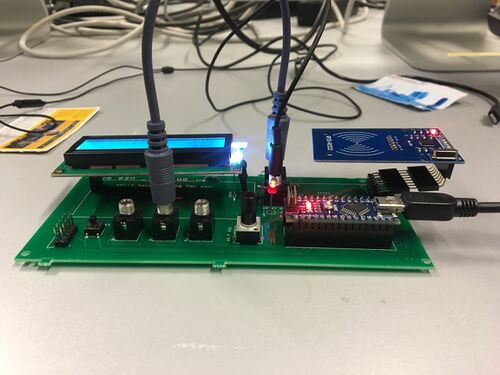
[[File:Txx.uo_Final.jpeg|500px|right]] | |||
Revision as of 19:44, 6 December 2019
Collaboration, Conflict & Consent
A two-day workshop with Eleanor Greenhalgh
_ Applying various methods of decision-making and evaluating the outcomes.
_ Practicing listening in teams of three [each having a specific role].
_ Playing group games, like counting to 20.
_ Creating a consensual artwork.
Module
Building a module with a guest tutor Dennis de Bel
Txx.uo manual [draft]
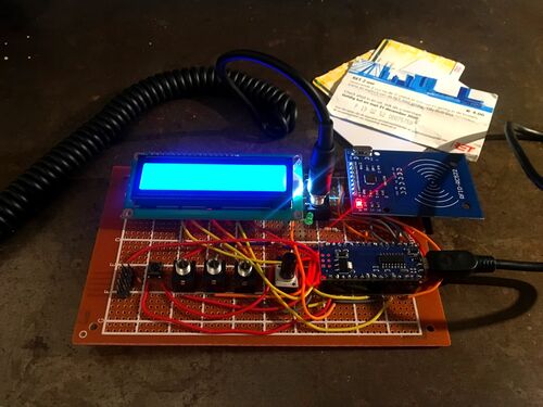
Txx.uo consolidates two contrasting radio frequency implementation modes: RFID reader scans the cards/objects containing RFID tags using radio waves and LCD screen displays a Q-code* [internationally established three-letter abbreviation used in radio communication].
*A particular Q-code denotes a question when it is followed by a question mark and references an answer [statement] when it's not:
QRU? : Have you anything for me?
QRU : I have nothing for you.
The RFID technology is used for object identification, authentication and security reasons, whereas Q-code is transmitted on a specific radio frequency by a radio operator and can be intercepted by anyone, who is tuned in to the same frequency.
This module converts the data received from a scanned card into a sound and binary code. This Binary signal is then transfigured into LED blinking and is also funneled to another module through an output channel. Top row of an LCD screen displays a specific question from the list of a Q-code, depending on a knob position and when receiving a signal from another module, a random Q-code answer is shown on the second row of the screen.
Components and configuration
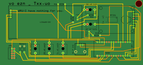
- PCB Txx.uo
- Arduino Nano
- 15x1 female header [x2] __ PCB
- 15x1 male header [x2] __ Arduino Nano
- 1602 I2C LCD display __ LCD1602-I2C
- RC522 RFID reader __ RFID1
- LED __ LED2 D7
- Vactrol
- LED __ LED14
- LDR __ LDR34
- Heat shrink tube
- 3.5mm mono jack socket [x5] __ D5 o1 Out1; D3 o2 Out1; T5 o3 Out1; A2 o4 Out1; D8 o5 Out1
- 10k ohm potentiometer __ A1 P in1
- Reset button __ Reset1
- 5x2 male header __ JP8
- 220 ohm resistor [x2] __ R55; R54
- 10k ohm resistor __ R56
- 8 Pins female header [11mm Pin][x3] _ RFID


