User:Alessia/Pen plotter music: Difference between revisions
(Add images to gallery and shuffle layout to allow for explanations woven through) |
m (Fix typo and add words) |
||
| (One intermediate revision by the same user not shown) | |||
| Line 16: | Line 16: | ||
--> | --> | ||
{|align=center | {|align=center | ||
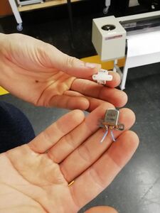
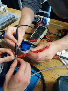
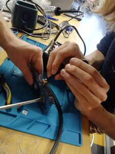
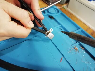
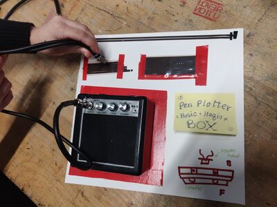
|colspan="3"|<center>We got two tape heads: one stereo reader head and one eraser head. The reader head | |colspan="3"|<center>We got two tape heads: one stereo reader head and one eraser head. The reader head has 4 pins, one set of 2 connected pins for the left channel and one set for the right channel. With a multimeter, we can check the resistance to find out which two pins are connected.</center> | ||
|- | |- | ||
|[[File:Thijs_hands.jpg|225px|frameless]] | |[[File:Thijs_hands.jpg|225px|frameless]] | ||
| Line 34: | Line 34: | ||
|[[File:pen_plotter_music_8.jpg|400px|frameless]] | |[[File:pen_plotter_music_8.jpg|400px|frameless]] | ||
|} | |} | ||
{{#Widget:Video|mp4=https://pzwiki.wdka.nl/mw-mediadesign/images/1/16/Pen_plotter_music9.mp4|style=width:225px;float:left;}} | |||
Latest revision as of 10:56, 18 October 2024
17 Oct cutting, soldering, taping
