User:Anita!/Special Issue 24 notes/knitting sound: Difference between revisions
No edit summary |
|||
| (2 intermediate revisions by the same user not shown) | |||
| Line 69: | Line 69: | ||
===Relation to a wider context=== | ===Relation to a wider context=== | ||
Does machine find the city overwhelming? or does it find it soothing? how can this be interpreted by simply looking at fabric? | Does machine find the city overwhelming? or does it find it soothing? how can this be interpreted by simply looking at fabric? | ||
===Further prototyping=== | |||
After looking into it a bit more, the 'computer' in the knitting machine is not really a computer, so I started working with the punch card machine instead, trying to write a script that will let me know, based on the nominal data received from the sensor (yes noise, no noise) which squares will be knitted in a particular colour by the machine. | |||
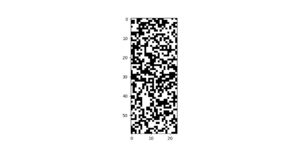
Trial python script not connected to the sensor: | |||
import matplotlib.pyplot as plt | |||
import numpy as np | |||
rows, cols = 60, 24 | |||
data = np.random.choice(['yes', 'no'], size=(rows, cols)) | |||
binary_data = np.where(data == 'yes', 1, 0) | |||
plt.figure(figsize=(10, 5)) | |||
plt.imshow(binary_data, cmap='gray', interpolation='none') | |||
plt.show() | |||
[[File:Result of running that script.png|thumb|Result of running that script]] | |||
Python script to transform the inputs received from the sensor into a black and white grid: | |||
import serial | |||
import matplotlib.pyplot as plt | |||
import numpy as np | |||
import time | |||
ser = serial.Serial('/dev/cu.usbserial-1130', 115200, timeout=1) | |||
data = [] | |||
rows, cols = 60, 24 | |||
def read_from_arduino(): | |||
while len(data) < rows * cols: | |||
line = ser.readline().decode('utf-8').strip() | |||
if line: | |||
data.append(line) | |||
print(f"Received: {line}") | |||
ser.close() | |||
return data | |||
data = read_from_arduino() | |||
matrix = np.array(data).reshape(rows, cols) | |||
binary_matrix = np.where(matrix == 'yes', 1, 0) | |||
plt.figure(figsize=(10, 5)) | |||
plt.imshow(binary_matrix, cmap='gray', interpolation='none') | |||
plt.show() | |||
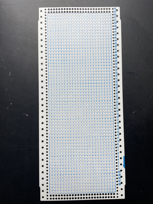
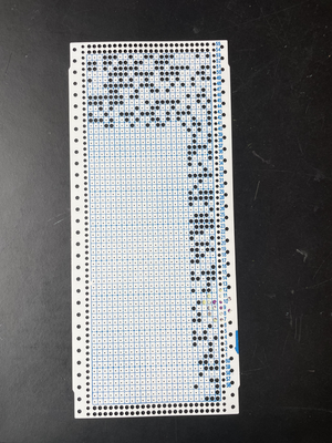
This is all based on a punch card i got at the fabric station. | |||
{|style="margin: 0 auto;" | |||
|[[File:Punch card.png|thumb|alt=Punch card for the knitting machine, it is unused and has a printed grid (24x60 squares))|Punch card]] | |||
|[[File:Punched card.png|thumb|alt=Punched card|Punched card]] | |||
|} | |||
This is the arduino code for the listening sensor: | |||
#define VCC 5.0 | |||
#define GND 0.0 | |||
#define ADC 1023.0 | |||
const int sensorPin = 33; | |||
float voltage; | |||
void setup() { | |||
Serial.begin(115200); | |||
} | |||
void loop() { | |||
voltage = GND + VCC*analogRead(sensorPin)/ADC; | |||
if (voltage > 160){ | |||
Serial.println("yes"); | |||
} | |||
else { | |||
Serial.println ("no"); | |||
} | |||
delay(100); | |||
} | |||
Also took a look at OpenSCAD, a software to 3D model with code, using a code from [https://mathgrrl.com/hacktastic/2019/05/punch-card-knitting-machine-patterns-with-openscad/ here] to model a punch card and its pattern. I think maybe though it is easier to use the python script directly because I don't understand the code that much. | |||
Latest revision as of 13:23, 29 May 2024
Knitting city noise is a part of the Project that may or may not be made
I want to connect a digital knitting machine (that has a small computer inside of it) to a sound sensor. This sensor will react to the sounds around it (city noise) and switch the colour of the yarn that is being used, creating a distinct fabric for each event that is being listened to.
This could be done by placing the sensors in different locations, listening to the sounds of the city and looking at the codes and machines interpretation visually translated into a fabric. Using the fabrics to imagine what city experience they refer to, heavy traffic, the sound of a tram passing by, a metro announcement, wind between tall buildings, loitering, construction etc.
The ideal outcome for this would be showing the fabrics in an installation setting, showing the fabrics possibly in connection to the sounds they come from.
Why make it?
Making a visual output to city noise. Looking at noise, mixing two senses and trying to capture the sonority of being in a busy city, and how the machine perceives it through a visual output.
Also on a more personal objective perspective, practising using arduino and sensors, connecting my interest for garment making techniques and fabrics with technology
Workflow
Identifying and choosing city noise. Researching and learning about how digital knitting machines work, more specifically, looking at the brother electroknit kh-940 since it is the one available to me in the fashion station. Based on my findings, programming the code for the sensor to listen and then change the colour of yarn when it hears noise. Testing the results on the machine, making adjustments on the sensitivity of the sensor. Knitting several different fabrics based on different city noise and observing the differences between them.
Timetable
Two maybe three weeks? I feel like once the code works it should not take long to put together. It is not that ambitious of a project I think.
Rapid prototypes
Connecting the sound sensor (from prototyping class):
#define VCC 5.0
#define GND 0.0
#define ADC 1023.0
const int sensorPin = 34;
float voltage;
void setup() {
 Serial.begin(115200);
}
void loop() {
 voltage = GND + VCC*analogRead(sensorPin)/ADC;
 Serial.println(voltage);
}
Recording quickly made on my phone on Blaak:
Sound of an ambulance passing by
Intersection noise
Tram coming, stopping and leaving
A visual (hand drawn) interpretation:
Previous practice
My practice often references and includes elements from fashion and fabric manufacturing techniques.
Relation to a wider context
Does machine find the city overwhelming? or does it find it soothing? how can this be interpreted by simply looking at fabric?
Further prototyping
After looking into it a bit more, the 'computer' in the knitting machine is not really a computer, so I started working with the punch card machine instead, trying to write a script that will let me know, based on the nominal data received from the sensor (yes noise, no noise) which squares will be knitted in a particular colour by the machine.
Trial python script not connected to the sensor:
import matplotlib.pyplot as plt
import numpy as np
rows, cols = 60, 24
data = np.random.choice(['yes', 'no'], size=(rows, cols))
binary_data = np.where(data == 'yes', 1, 0)
plt.figure(figsize=(10, 5))
plt.imshow(binary_data, cmap='gray', interpolation='none')
plt.show()
Python script to transform the inputs received from the sensor into a black and white grid:
import serial
import matplotlib.pyplot as plt
import numpy as np
import time
ser = serial.Serial('/dev/cu.usbserial-1130', 115200, timeout=1)
data = []
rows, cols = 60, 24
def read_from_arduino():
   while len(data) < rows * cols:
       line = ser.readline().decode('utf-8').strip()
       if line:
           data.append(line)
           print(f"Received: {line}")
   ser.close()
   return data
data = read_from_arduino()
matrix = np.array(data).reshape(rows, cols)
binary_matrix = np.where(matrix == 'yes', 1, 0)
plt.figure(figsize=(10, 5))
plt.imshow(binary_matrix, cmap='gray', interpolation='none')
plt.show()
This is all based on a punch card i got at the fabric station.
This is the arduino code for the listening sensor:
#define VCC 5.0
#define GND 0.0
#define ADC 1023.0
const int sensorPin = 33;
float voltage;
void setup() {
 Serial.begin(115200);
}
void loop() {
voltage = GND + VCC*analogRead(sensorPin)/ADC;
if (voltage > 160){
 Serial.println("yes");
}
 else {
   Serial.println ("no");
 }
delay(100);
}
Also took a look at OpenSCAD, a software to 3D model with code, using a code from here to model a punch card and its pattern. I think maybe though it is easier to use the python script directly because I don't understand the code that much.


