Arduino101: Difference between revisions
No edit summary |
|||
| (31 intermediate revisions by the same user not shown) | |||
| Line 8: | Line 8: | ||
NOTE: Arduino clones need a special driver, see [http://pzwiki.wdka.nl/mediadesign/Arduino101#Driver below]. | NOTE: Arduino clones need a special driver, see [http://pzwiki.wdka.nl/mediadesign/Arduino101#Driver below]. | ||
== Graphical == | === Graphical === | ||
All Platforms (Windows/OSX/Linux) >> Download the IDE here: https://www.arduino.cc/en/Main/Software | All Platforms (Windows/OSX/Linux) >> Download the IDE here: https://www.arduino.cc/en/Main/Software | ||
| Line 20: | Line 20: | ||
https://www.instructables.com/id/Install-Arduino-IDE-182-on-Linux/ | https://www.instructables.com/id/Install-Arduino-IDE-182-on-Linux/ | ||
== Command Line == | === Command Line === | ||
First, install the Graphical IDE, then: | First, install the Graphical IDE, then: | ||
https://github.com/sudar/Arduino-Makefile <br><br> | https://github.com/sudar/Arduino-Makefile <br><br> | ||
See also: https://git.xpub.nl/XPUB/special-issue-x/src/branch/master/templates/arduino-make and https://git.xpub.nl/XPUB/special-issue-x/src/branch/master/templates/bare-make | See also: https://git.xpub.nl/XPUB/special-issue-x/src/branch/master/templates/arduino-make and https://git.xpub.nl/XPUB/special-issue-x/src/branch/master/templates/bare-make | ||
== Driver == | === Driver === | ||
WIN+OSX:http://sparks.gogo.co.nz/ch340.html | WIN+OSX:http://sparks.gogo.co.nz/ch340.html | ||
== Web == | '''Note:''' | ||
OSX Yosemite (10.10.2): https://github.com/MPParsley/ch340g-ch34g-ch34x-mac-os-x-driver/blob/master/CH34x_Install_V1.3.pkg<br> | |||
OSX Mojave has the driver built in. <br> | |||
Recent Linux flavours have the driver built in. <br> | |||
=== Web === | |||
https://www.circuito.io/ | https://www.circuito.io/ | ||
https://create.arduino.cc/editor | https://create.arduino.cc/editor | ||
=== NOTE BEFORE CONNECTING YOUR ARDUINO === | |||
Most Arduino (compatible) boards have there electronic components exposed (on the bottom). '''DO NOT PUT THE ARDUINO ON TOP OF YOUR LAPTOP''' You won't be the first to destroy your arduino by short circuiting it with the case of your laptop, even most plastic laptops actually have magnesium alloy type of cases which conduct electricity! | |||
== Hardware == | === Hardware === | ||
To program (or flash) your arduino, you need to connect it to your computer (using USB). Connect your Arduino, open the Arduino IDE and see if your board appears:<br><br> | To program (or flash) your arduino, you need to connect it to your computer (using USB). Connect your Arduino, open the Arduino IDE and see if your board appears:<br><br> | ||
| Line 54: | Line 60: | ||
[[File:Arduino-bootloader.png|frameless]]<br> | [[File:Arduino-bootloader.png|frameless]]<br> | ||
''Screenshot showing clone Arduino Nano 'bootloader' options on OSX.'' | ''Screenshot showing clone Arduino Nano 'bootloader' options on OSX.'' | ||
=== Test!=== | |||
Open one of the examples found in the Arduino IDE to test your connection with the Arduino board, for example Blink, which will blink the onboard LED (pin 13) on and off. Go to File > Examples > 01. Basics > Blink and upload it to your board! Alternatively use the code below: | |||
<pre> | |||
// the setup function runs once when you press reset or power the board | |||
void setup() { | |||
// initialize digital pin LED_BUILTIN as an output. LED_BUILTIN is the same as using the number 13, indicating digital pin 13 | |||
pinMode(LED_BUILTIN, OUTPUT); | |||
} | |||
// the loop function runs over and over again forever | |||
void loop() { | |||
digitalWrite(LED_BUILTIN, HIGH); // turn the LED on (HIGH is the voltage level) | |||
delay(1000); // wait for a second | |||
digitalWrite(LED_BUILTIN, LOW); // turn the LED off by making the voltage LOW | |||
delay(1000); // wait for a second | |||
} | |||
</pre> | |||
== Sketches == | == Sketches == | ||
| Line 70: | Line 94: | ||
} | } | ||
</pre> | </pre> | ||
==== Functions ==== | |||
Functions are indicated by a name and (), so; thiscouldbeafunction(). What is inside the curly brackets {}, is actually executed/run/performed. For example: | |||
<pre> | |||
char hello(){ | |||
Serial.println("hallo!!"); | |||
} | |||
</pre> | |||
Functions can take arguments: hello(input){} and return an output, "hallo!" in this case. The code above by itself is not executed. To execute a function you 'call' it: hello(); | |||
Read more [https://www.arduino.cc/en/Reference/FunctionDeclaration here]. | |||
==== Void ==== | ==== Void ==== | ||
| Line 92: | Line 129: | ||
Add milliseconds delay to your loop, Arduino runs at 4, 8 or 16MHz...thats too fast to see! | Add milliseconds delay to your loop, Arduino runs at 4, 8 or 16MHz...thats too fast to see! | ||
=== Debugging === | === Debugging using Serial Monitor === | ||
To see if your code is running, or to see what values are being read by the inputs or send to the outputs you can activate the ''serial console''. Add the following code in in the setup() function:<br> | To see if your code is running, or to see what values are being read by the inputs or send to the outputs you can activate the ''serial console''. Add the following code in in the setup() function:<br> | ||
<pre> | <pre> | ||
| Line 108: | Line 145: | ||
[[File:Arduino-serial-monitor0.png|frameless]] | [[File:Arduino-serial-monitor0.png|frameless]] | ||
''Activate monitor after uploading your code'' | |||
<br> | <br> | ||
[[File:Arduino-serial-monitor1.png|frameless]] | [[File:Arduino-serial-monitor1.png|frameless]] | ||
Output of the above code | ''Output of the above code'' | ||
You can also get the serial output in a terminal, see [https://learn.sparkfun.com/tutorials/terminal-basics/command-line-windows-mac-linux here]. | |||
=== Basic Loops: For === | === Basic Loops: For === | ||
| Line 217: | Line 256: | ||
=Prototyping= | =Prototyping= | ||
==Hardware Summary== | |||
[[File:Arduino-ports.jpg|700px|frameless]] | |||
Analog IN: Input only. Analog to Digital Converter > 0-5v, converted to 0-1023 | |||
-function: analogRead(); | |||
Digital: Input and output | |||
digitalRead(); // measure if something is on or off (HIGH, or LOW, ~0-5v) | |||
digitalWrite();// set port HIGH or LOW (on or off, ~0-5v) | |||
analogWrite(); // pwm output (fake analog) | |||
==Electronics Basics== | |||
===Electricity=== | |||
*Static electricity: Balloons, equilibrium > friction > change of potential > discharge <br> | |||
*Current electricity: Moving electrons. Circuit: power source + conductor + resistor (else short circuit: friction/heat/fire)<br><br> | |||
An nice analogy for current electricity is plumbing: The (water) pressure on the tubes is the Voltage. The speed at which the water flows is the Current. A resistor slows down electrons: its like a choke/restriction in a water tube, reducing the flow of water. | |||
Adafruit has some nice visualisations of these principles: https://learn.sparkfun.com/tutorials/voltage-current-resistance-and-ohms-law/all | |||
Handy for prototyping: Circuito https://www.circuito.io/ WARNING: this app is 'stupid' and cant guess what you want to make. The site also generates code for you, but this is best avoided since it results in exorbitant amounts of unintuitive code. | |||
==Breadboard== | ==Breadboard== | ||
[[File:Breadboard101.png|frameless]]<br> | [[File:Breadboard101.png|frameless]]<br> | ||
''Solderless breadboard, (hand drawn) red lines indicate interconnected contacts'' | ''Solderless breadboard, (hand drawn) red lines indicate interconnected contacts'' | ||
==Input== | [[File:bb-powerrails.png|frameless]]<br> | ||
''Most breadboards have 'power rails' on both sides. Connect the arduino's 5v to the red (positive) and ground to the blue/black (ground) rails. Now you have easy access to 5 volts on the whole breadboard.'' | |||
==Input/Output== | |||
Arduino has 'Analog' and 'Digital' pins. The analog pins are connected to an ADC, analog-to-digital-converter and in general are INPUTS (there are some exceptions). They convert a VOLTAGE to numbers: 0-5v > 0-1023. The digital pins are inputs as well as outputs. They accept 0-5volts as input and can output 0 OR 5 volts. Some digital pins can generate a PWM signal to 'simulate' analog voltages through rapidly switching on and off (analogWrite). The digital pins have two states: HIGH or LOW. As output this means 0 volts when LOW and 5 volts when HIGH. As input LOW is when the input is between 0 V and 0.8 V and "high" when the input is between 2.2 V and 5 V. | |||
Arduino enables you to interface with the world outside of your computer. As input you can use various 'sensors' to turn the physical world into digital numbers. A lot of sensors are actually variable resistors like a potentiometer. Their resistance though will change according to changes in light, temperature, humidity, mechanical stress (push buttons, bend sensors, piezo's). | |||
===Voltage divider=== | |||
The inputs of an Arduino can ONLY measure changes in voltage, not resistance. Many sensors behave like variable resistors; they don't produce any voltage! If you shine a light on a Light Dependant Resistor of LDR (see below), it wont produce a measurable voltage. Same goes for pressing a button; it is a ''passive'' component. | |||
[[File:Voltage-divider-circuit.png|framelessl]] | |||
Using the built-in power source of Arduino (Vin, 5v and/or 3.3v) and an additional resistor (R2) with the 'sensor' (R1) we can create a ''voltage divider '' circuit, that, when the resistance of the sensor (R1) changes, a change in (measurable) voltage occurs in between the point indicated as Vout in the image above. For practical wiring examples and applications, scroll down. | |||
For the theory we have to look at Ohm's law and how resistors behave in various configurations. | |||
==== Series ==== | |||
[[File:Seriesresistor.gif|framelessl]] | |||
*Rtotal = R1+R2+R3 | |||
*Current is the same at each resistor | |||
*''Voltage differs'' > this use useful for arduino, since it can only measure voltage! (confusingly current is measured in series with circuit, voltage is measured parallel > adding components/circuity to arduino is alway parallel to the arduino itself ) | |||
==== Parallel ==== | |||
[[File:Paralellresistors.gif|framelessl]] | |||
*1/Rtotal = 1/R1+1/R2+1/R3 | |||
*Voltage is the same at each resistor | |||
*''Current differs'' | |||
===Pushbutton=== | ===Pushbutton=== | ||
[[File:Arduino-pushbutton-1-10k.png|frameless]] | |||
''images via https://circuito.io'' | |||
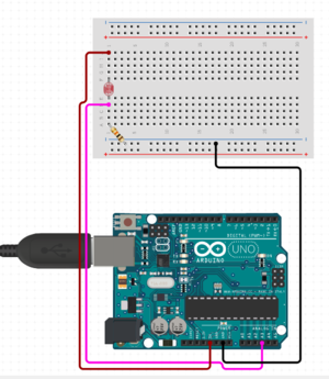
===LDR=== | |||
Variable resistor (light). Application: Fake Theremin, reacting to (phone) screen (light 'sequencer') | |||
[[File:Arduino-ldr-1-10k.png|frameless]] | |||
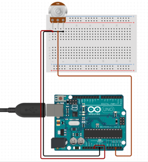
===Potentiometer=== | ===Potentiometer=== | ||
Variable resistor (mechanical) | Variable resistor (mechanical). A potentiometer is, itself a voltage divider circuit, just trace the 3 pins: | ||
[[File:Arduino-potmeter-1-10k.png|frameless]] | |||
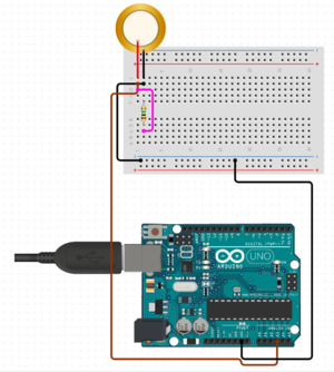
===Piezo as Sensor=== | |||
A piezo produce a current when hit ('mechanically stressed'). The harder you hit, the more voltage and current it produces. You need to connect a 1M Ohm resistor parallel to it's positive and negative terminal (Polarity!) to limit the voltage and current produced by the piezo and to protect the analog input. (Read more [https://www.arduino.cc/en/tutorial/knock here]). | |||
[[File:Arduino-piezo-1m.png|frameless]] | |||
===Piezo as Speaker=== | |||
A piezo produce a current when hit ('mechanically stressed') but when you apply a current it will start to vibrate. One pin to digital ~ port and ground is enough to make sounds using the Tone() function/lib. | |||
===Antenna=== | |||
Antenna, or random wire antenna, is a ...random length of wire attached to one of the digital pins. Set it as input and the sensitivity of the digital ports will even register small changes in electrical fields, induced, for example by laptops, phones, chargers. Example [https://create.arduino.cc/projecthub/PatelDarshil/arduino-emf-detector-a-k-a-ghost-detector-7ce085 here] | |||
=== | ===Gas=== | ||
There is a gas sensor...wow. | |||
=== Smoothing in Software === | === Smoothing in Software === | ||
Input values are never stable. To smooth out the incoming signals you can smooth them out a bit like this: smoothing and filtering: https://www.megunolink.com/articles/coding/3-methods-filter-noisy-arduino-measurements/ | |||
Also you can 'map' ranges of values to other values, see https://www.arduino.cc/reference/en/language/functions/math/map/ | |||
==Output== | ==Output== | ||
| Line 259: | Line 370: | ||
</pre> | </pre> | ||
=== Protect ya Led: External LED === | |||
A LED (Light Emitting Diode) is a diode and thus has polarity. In one direction it blocks current and the other direction allows infinite current. This infinite current thirst can cause the LED to burn through. We must limit the current using a resistor (even a 3v battery can destroy a LED when connected directly): <br> | A LED (Light Emitting Diode) is a diode and thus has polarity. In one direction it blocks current and the other direction allows infinite current. This infinite current thirst can cause the LED to burn through. We must limit the current using a resistor (even a 3v battery can destroy a LED when connected directly): <br> | ||
[[File:Arduino-uno-circuito-led.png|frameless]] | [[File:Arduino-uno-circuito-led.png|frameless]] | ||
| Line 297: | Line 408: | ||
(Tone?) | (Tone?) | ||
Arduino UNO > http://highlowtech.org/?p=1963 | Arduino UNO > http://highlowtech.org/?p=1963 | ||
=== Displays === | |||
There are many kinds of displays (7 segment, led, lcd, tft) and equally many ways of hooking them up to an arduino. | |||
If you want to use a display in combination with sound, be sure pin D11 is not used by the screen (or generate sound on a different pin....). | |||
== Combine Input and Output == | |||
=== LDR + Piezo Buzzer/speaker === | |||
Fake [https://www.youtube.com/watch?v=K6KbEnGnymk theremin] | |||
=== Servo + Pot === | |||
Control servo (output) with potentiometer (input) | |||
*See: Arduino > File > Examples > Servo > Knob | |||
---- | |||
===DAC=== | ===DAC=== | ||
Latest revision as of 13:30, 6 October 2021
Arduino is umbrella term for a collection of programmable microcontrollers. These microcontrollers allows you to easily interface the physical world of knobs and 'sensors' with code. The term 'arduino' covers both a physical device and an integrated development environment (IDE) that allows you to write, review, debug and upload code to your microcontroller. The Arduino IDE supports a wide variety of microcontrollers from different manufacturers with equally varying specifications (ATMEL, ESP32, ESP8266, etc). The original Arduino project takes a bare 8 bit microcontroller and adds an USB port (+ usb-to-serial converter by FTDI), voltage regulators, input/output header pins for plug and play experience. It's schematics are open source and allowed the proliferation of many varieties and clones. It is also very easy (and cheap) to make your own 'Arduino' clone on a breadboard with a handful of components.
Software
NOTE: Arduino clones need a special driver, see below.
Graphical
All Platforms (Windows/OSX/Linux) >> Download the IDE here: https://www.arduino.cc/en/Main/Software
Installation OSX Unpack, mount, drag to applications folder
Installation Win Run installer, follow installation procedure.
Installation Linux https://www.instructables.com/id/Install-Arduino-IDE-182-on-Linux/
Command Line
First, install the Graphical IDE, then:
https://github.com/sudar/Arduino-Makefile
See also: https://git.xpub.nl/XPUB/special-issue-x/src/branch/master/templates/arduino-make and https://git.xpub.nl/XPUB/special-issue-x/src/branch/master/templates/bare-make
Driver
WIN+OSX:http://sparks.gogo.co.nz/ch340.html
Note:
OSX Yosemite (10.10.2): https://github.com/MPParsley/ch340g-ch34g-ch34x-mac-os-x-driver/blob/master/CH34x_Install_V1.3.pkg
OSX Mojave has the driver built in.
Recent Linux flavours have the driver built in.
Web
https://www.circuito.io/ https://create.arduino.cc/editor
NOTE BEFORE CONNECTING YOUR ARDUINO
Most Arduino (compatible) boards have there electronic components exposed (on the bottom). DO NOT PUT THE ARDUINO ON TOP OF YOUR LAPTOP You won't be the first to destroy your arduino by short circuiting it with the case of your laptop, even most plastic laptops actually have magnesium alloy type of cases which conduct electricity!
Hardware
To program (or flash) your arduino, you need to connect it to your computer (using USB). Connect your Arduino, open the Arduino IDE and see if your board appears:
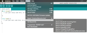
Screenshot showing original Arduino UNO connected to serial port on OSX.
Important settings
Board: Select the correct Arduino AVR Board from the list (UNO or Nano in our case). Note in the case of the Nano, there are 2 different chips, 328p and 328p (Old bootloader). If you get errors while uploading your sketch, play with this option.
Port: Select the right serial port to upload your sketch to:
linux: /dev/ttyACM# or /dev/ttyUSB (# = number)
osx: /dev/cu.wchusbserial# or dev/cu.usbmodem# (# = number)
win: COM# (# = number)
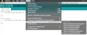
Screenshot showing clone Arduino Nano connected to serial port on OSX.
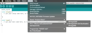
Screenshot showing clone Arduino Nano 'bootloader' options on OSX.
Test!
Open one of the examples found in the Arduino IDE to test your connection with the Arduino board, for example Blink, which will blink the onboard LED (pin 13) on and off. Go to File > Examples > 01. Basics > Blink and upload it to your board! Alternatively use the code below:
// the setup function runs once when you press reset or power the board
void setup() {
  // initialize digital pin LED_BUILTIN as an output. LED_BUILTIN is the same as using the number 13, indicating digital pin 13
  pinMode(LED_BUILTIN, OUTPUT);
}

// the loop function runs over and over again forever
void loop() {
  digitalWrite(LED_BUILTIN, HIGH);   // turn the LED on (HIGH is the voltage level)
  delay(1000);                       // wait for a second
  digitalWrite(LED_BUILTIN, LOW);    // turn the LED off by making the voltage LOW
  delay(1000);                       // wait for a second
}
Sketches
Anatomy of a sketch
Arduino programs/firmware are called 'sketches'. The language used it a variant of C/C++. When you open a new sketch (File > New), you are presented with the following code:
void setup() {
  // put your setup code here, to run once:

}

void loop() {
  // put your main code here, to run repeatedly:

}
Functions
Functions are indicated by a name and (), so; thiscouldbeafunction(). What is inside the curly brackets {}, is actually executed/run/performed. For example:
char hello(){
 Serial.println("hallo!!");
}
Functions can take arguments: hello(input){} and return an output, "hallo!" in this case. The code above by itself is not executed. To execute a function you 'call' it: hello(); Read more here.
Void
Void defines a function that does not return any values after being executed.
Setup()
Setup is a function that is only run once, when the arduino is powered on. Everything inside is executed only once.
Loop()
Loop, is an ever repeating function while the Arduino is powered on. Everything inside is repeated over and over. Loop, is an ever re....
Comments
To add notes/instructions or to temporary disable a piece of code you can use comments. Indicated by the double forward slashes: //
Semicolon
Every line ends with a semicolon: ;
Variables
Entities used for (dynamically) storing values, strings etc. int, float, char.
Delay()
Add milliseconds delay to your loop, Arduino runs at 4, 8 or 16MHz...thats too fast to see!
Debugging using Serial Monitor
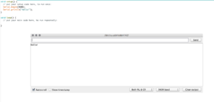
To see if your code is running, or to see what values are being read by the inputs or send to the outputs you can activate the serial console. Add the following code in in the setup() function:
void setup() {
  // put your setup code here, to run once:
  Serial.begin(9600);
  Serial.println("hello!");
}

void loop() {
  // put your main code here, to run repeatedly:

}
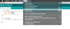 Activate monitor after uploading your code
You can also get the serial output in a terminal, see here.
Basic Loops: For
void setup() {
  // put your setup code here, to run once:
  Serial.begin(9600);
  Serial.println("hello!");
}

void loop() {
  // put your main code here, to run repeatedly:
  for (int i = 0; i <= 255; i++) {
      Serial.println(i);
    delay(100); // pause loop for 100ms
  }

}
second for loop
char z[] = "words are fun!"; //14 character

void setup() {
  Serial.begin(9600);
}
void loop() {

  for(int x=0;x<15;x++){
    Serial.println(x);
    delay(200);
  }

}
Basic Loops: While
char z[] = "words are fun!"; //14 character
int x=0;

void setup() {
  Serial.begin(9600);
}
void loop() {

    while(x<15){
      Serial.println(z[x]);
      delay(100); // pause loop for 100ms
      x++; //x + 1 + 1
    }
}
Basic Control Structures: If
void setup() {
  // put your setup code here, to run once:
  Serial.begin(9600);
  Serial.println("hello!");
}

void loop() {
  // put your main code here, to run repeatedly:
  for (int i = 0; i <= 255; i++) {
    if (i == 100) {
      // if count is 100, do something!
    }
    delay(20); // pause loop for 100ms
  }

}
Exercise: make the serial monitor say something when count is below 100, when count is 100 and when count is higher than 100.
hints: https://www.arduino.cc/reference/en/language/structure/control-structure/if/
Basic Control Structures: If....Else
char z[] = "words are fun!"; //14 character

void setup() {
  Serial.begin(9600);
}
void loop() {

  for(int x=0;x<15;x++){
    if(x == 7){
      Serial.println("Were Lucky!");
     } else {
      Serial.println(x);
     }
    delay(200);
  }

}
Arduino + Processing
Using Serial for Visualising, also add cli way (for more flexible/modular approach(promoting approaches not apps))! https://learn.sparkfun.com/tutorials/connecting-arduino-to-processing/all
Prototyping
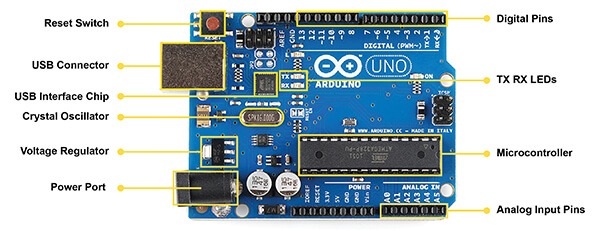
Hardware Summary
Analog IN: Input only. Analog to Digital Converter > 0-5v, converted to 0-1023 -function: analogRead();
Digital: Input and output digitalRead(); // measure if something is on or off (HIGH, or LOW, ~0-5v) digitalWrite();// set port HIGH or LOW (on or off, ~0-5v) analogWrite(); // pwm output (fake analog)
Electronics Basics
Electricity
- Static electricity: Balloons, equilibrium > friction > change of potential > discharge
- Current electricity: Moving electrons. Circuit: power source + conductor + resistor (else short circuit: friction/heat/fire)
An nice analogy for current electricity is plumbing: The (water) pressure on the tubes is the Voltage. The speed at which the water flows is the Current. A resistor slows down electrons: its like a choke/restriction in a water tube, reducing the flow of water.
Adafruit has some nice visualisations of these principles: https://learn.sparkfun.com/tutorials/voltage-current-resistance-and-ohms-law/all
Handy for prototyping: Circuito https://www.circuito.io/ WARNING: this app is 'stupid' and cant guess what you want to make. The site also generates code for you, but this is best avoided since it results in exorbitant amounts of unintuitive code.
Breadboard
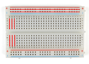
Solderless breadboard, (hand drawn) red lines indicate interconnected contacts
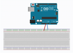
Most breadboards have 'power rails' on both sides. Connect the arduino's 5v to the red (positive) and ground to the blue/black (ground) rails. Now you have easy access to 5 volts on the whole breadboard.
Input/Output
Arduino has 'Analog' and 'Digital' pins. The analog pins are connected to an ADC, analog-to-digital-converter and in general are INPUTS (there are some exceptions). They convert a VOLTAGE to numbers: 0-5v > 0-1023. The digital pins are inputs as well as outputs. They accept 0-5volts as input and can output 0 OR 5 volts. Some digital pins can generate a PWM signal to 'simulate' analog voltages through rapidly switching on and off (analogWrite). The digital pins have two states: HIGH or LOW. As output this means 0 volts when LOW and 5 volts when HIGH. As input LOW is when the input is between 0 V and 0.8 V and "high" when the input is between 2.2 V and 5 V.
Arduino enables you to interface with the world outside of your computer. As input you can use various 'sensors' to turn the physical world into digital numbers. A lot of sensors are actually variable resistors like a potentiometer. Their resistance though will change according to changes in light, temperature, humidity, mechanical stress (push buttons, bend sensors, piezo's).
Voltage divider
The inputs of an Arduino can ONLY measure changes in voltage, not resistance. Many sensors behave like variable resistors; they don't produce any voltage! If you shine a light on a Light Dependant Resistor of LDR (see below), it wont produce a measurable voltage. Same goes for pressing a button; it is a passive component.
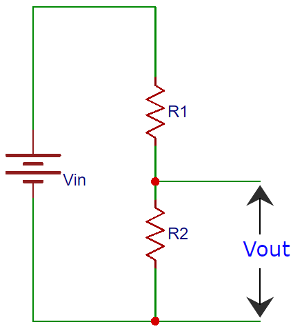
Using the built-in power source of Arduino (Vin, 5v and/or 3.3v) and an additional resistor (R2) with the 'sensor' (R1) we can create a voltage divider circuit, that, when the resistance of the sensor (R1) changes, a change in (measurable) voltage occurs in between the point indicated as Vout in the image above. For practical wiring examples and applications, scroll down.
For the theory we have to look at Ohm's law and how resistors behave in various configurations.
Series
- Rtotal = R1+R2+R3
- Current is the same at each resistor
- Voltage differs > this use useful for arduino, since it can only measure voltage! (confusingly current is measured in series with circuit, voltage is measured parallel > adding components/circuity to arduino is alway parallel to the arduino itself )
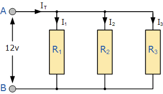
Parallel
- 1/Rtotal = 1/R1+1/R2+1/R3
- Voltage is the same at each resistor
- Current differs
Pushbutton
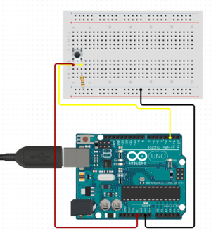 images via https://circuito.io
LDR
Variable resistor (light). Application: Fake Theremin, reacting to (phone) screen (light 'sequencer')
Potentiometer
Variable resistor (mechanical). A potentiometer is, itself a voltage divider circuit, just trace the 3 pins:
Piezo as Sensor
A piezo produce a current when hit ('mechanically stressed'). The harder you hit, the more voltage and current it produces. You need to connect a 1M Ohm resistor parallel to it's positive and negative terminal (Polarity!) to limit the voltage and current produced by the piezo and to protect the analog input. (Read more here).
Piezo as Speaker
A piezo produce a current when hit ('mechanically stressed') but when you apply a current it will start to vibrate. One pin to digital ~ port and ground is enough to make sounds using the Tone() function/lib.
Antenna
Antenna, or random wire antenna, is a ...random length of wire attached to one of the digital pins. Set it as input and the sensitivity of the digital ports will even register small changes in electrical fields, induced, for example by laptops, phones, chargers. Example here
Gas
There is a gas sensor...wow.
Smoothing in Software
Input values are never stable. To smooth out the incoming signals you can smooth them out a bit like this: smoothing and filtering: https://www.megunolink.com/articles/coding/3-methods-filter-noisy-arduino-measurements/ Also you can 'map' ranges of values to other values, see https://www.arduino.cc/reference/en/language/functions/math/map/
Output
Blinking LED
Blink a LED (every Arduino board has a built in LED):
// the setup function runs once when you press reset or power the board
void setup() {
  // initialize digital pin LED_BUILTIN as an output.
  pinMode(LED_BUILTIN, OUTPUT);
}

// the loop function runs over and over again forever
void loop() {
  digitalWrite(LED_BUILTIN, HIGH);   // turn the LED on (HIGH is the voltage level)
  delay(1000);                       // wait for a second
  digitalWrite(LED_BUILTIN, LOW);    // turn the LED off by making the voltage LOW
  delay(1000);                       // wait for a second
}
Protect ya Led: External LED
A LED (Light Emitting Diode) is a diode and thus has polarity. In one direction it blocks current and the other direction allows infinite current. This infinite current thirst can cause the LED to burn through. We must limit the current using a resistor (even a 3v battery can destroy a LED when connected directly):
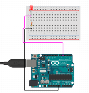 See online sketch here
Online Led protection resistance calculator and rationale
Beyond the Blink: Fading LED
int pwmPin = 11; //define output pin, chose pin with PWM out output indicated by a tilde (~), built in LED doesnt work

void setup() {
 pinMode(pwmPin, OUTPUT);
}

void loop() {

  for(int value = 0; value<=255; value++){
    analogWrite(pwmPin, value);
    delay(30);
    }

  delay(30);

  for(int value = 255; value>=0; value--){
     analogWrite(pwmPin, value);
    delay(30);
    }

  delay(10);

}
Credits: https://github.com/binaryupdates/PWM-With-Arduino
Sound
(Tone?) Arduino UNO > http://highlowtech.org/?p=1963
Displays
There are many kinds of displays (7 segment, led, lcd, tft) and equally many ways of hooking them up to an arduino. If you want to use a display in combination with sound, be sure pin D11 is not used by the screen (or generate sound on a different pin....).
Combine Input and Output
LDR + Piezo Buzzer/speaker
Fake theremin
Servo + Pot
Control servo (output) with potentiometer (input)
- See: Arduino > File > Examples > Servo > Knob
DAC
Arduino can convert analog signals (voltages) into 8 bit digital numbers (0-1023 using an 'ADC' or Analog to Digital converter). The arduino cannot output analog voltages only digital suqare waves in the shape of a PWM (Pulse Width Modulation) signal. To retireve analog voltages you need external hardware.
Simple Hardware
R2R ladder filter, RC Filter (filter harmonics from the pwm), https://provideyourown.com/2011/analogwrite-convert-pwm-to-voltage/
Intermediate Hardware
https://create.arduino.cc/projecthub/Arduino_Scuola/build-a-simple-dac-for-your-arduino-4c00bd.
Hard Hardware
https://www.electroschematics.com/arduino-dac-guide/
Considerations
Clones vs Real Deal
Clones use inferior usb to serial chips, voltage regulators and non removable atmel microcontrollers. With buying an original Arduino you support the development and community (needs proof ;p).

