PiezoPreamp
Piezo-disc Preamplifier Circuit
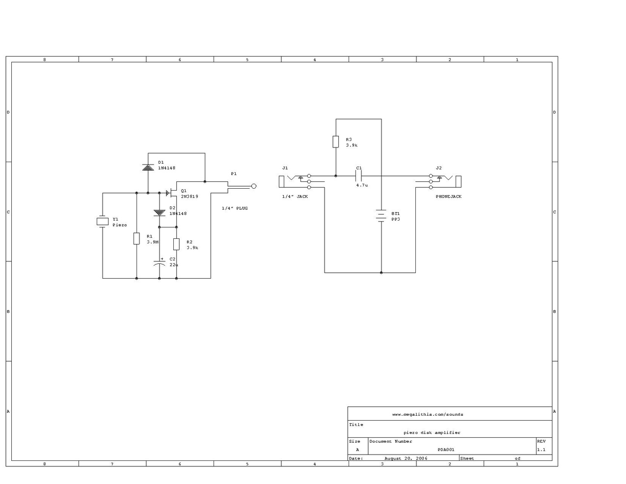
Attached is a PDF with a schematic drawing for a really simple preamplifier for piezo-disc type pickups/microphones.
The circuit consists of two halves:
- on the left is the preamp itself, built around a 2N3819 J-FET transistor with two diodes, two resistors and a capacitor. This circuit magically manages to get its power and carry its signal via the same wire (the tip of plug
P1
)
- on the right is the circuit that powers the preamplifier. It contains a 9V battery, a resistor and a capacitor to separate the signal from the powersupply. For a multi-channel version of this circuit, multiple amplifiers can be powered from one 9V battery, as long as each amplifier/channel has its own
R3
&
C1
power/signal splitter circuit.